Acer P1166 User Manual
Page 57
Confidential
2-
P1166 / P1266 / P1266i / P1166P / P1266P
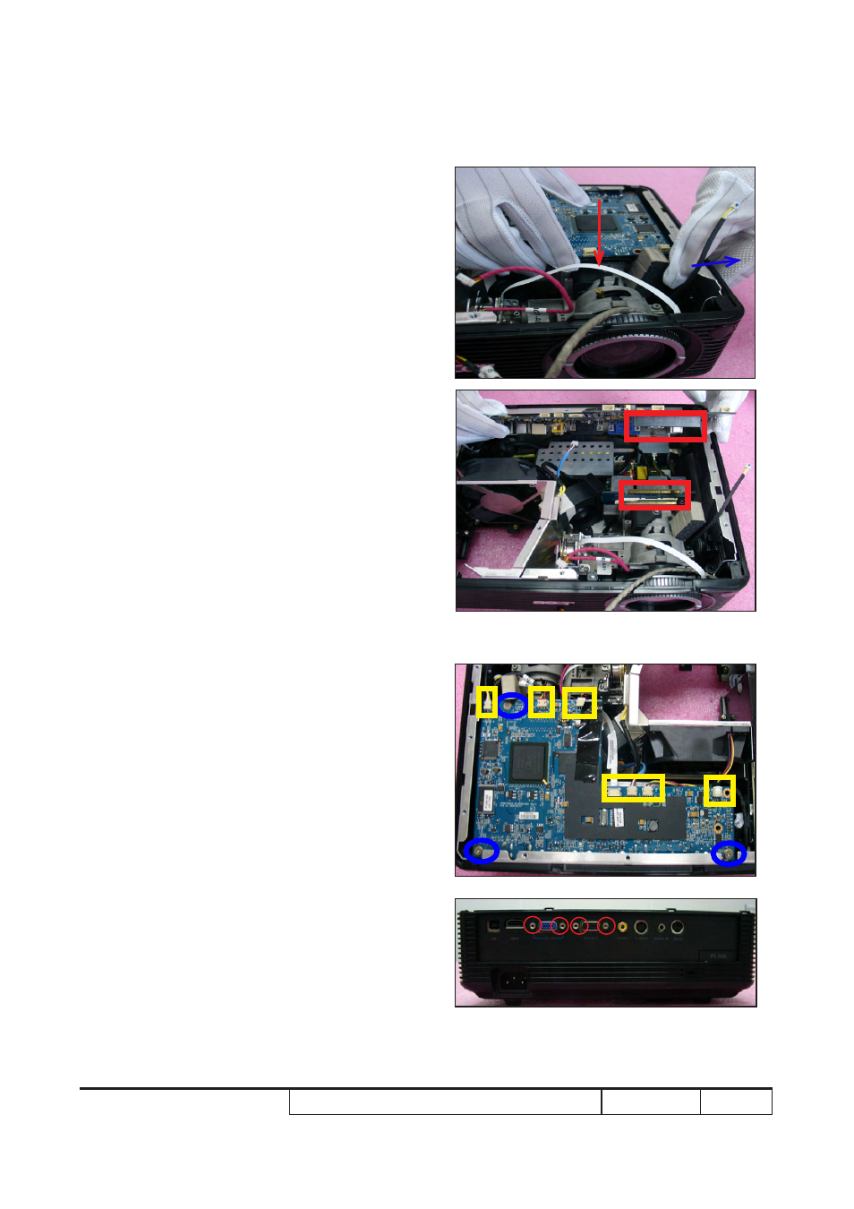
5. Plug 7 connecors (as yellow square).
6. Screw 3 screws (as blue circle).
7. Screw 4 hex screws (as red circle).
4. Press bottom support shielding as blue
arrow directs, push Main Board Module
as red arrow directs.
Note: The connector on the Main Board
should be connected to the DMD
Board (as red square) when
assembling Main Board.