Archive, Rf 1 fiber optic - installation, Open collector output – Ransburg RF1 FiberOptic Meter 77786-XX, A11516-XX User Manual
Page 18: Isolated output, Changing output configuration
FM-00-02.5
RF 1 Fiber Optic - Installation
Applications for Vin Logic would be standard
Industrial Control Circuitry. This is the configuration
that the receiver is shipped with from the factory .
Open Collector Output
Open Collector Output
Open Collector Output
Open Collector Output
Open Collector Output
In this output configuration the receiver provides
access to the collector of the output transistor.
The controller must provide a current limited voltage
source (+Voc) to the receiver outputs. The output
signals are as shown in Figure 8.
Figure 8: Open Collector Output
Figure 8: Open Collector Output
Figure 8: Open Collector Output
Figure 8: Open Collector Output
Figure 8: Open Collector Output
Applications for open collector outputs would be
for driving high speed counter cords on PLC’s.
Isolated Output
Isolated Output
Isolated Output
Isolated Output
Isolated Output
In this output configuration the receiver outputs
are galvanically isolated from the receiver power
supply and the reset of the receiver circuitry. In
this configuration the outputs behave like switches
except that current will only flow one way when
the switch is closed. This source of current must
be current limited to 50mA and supplied to the
receiver from the controller for use to simulate a
positive DC only relay. (Maximum DC voltage
must not exceed 30 volts.)
Figure 9: Isolated Output
Figure 9: Isolated Output
Figure 9: Isolated Output
Figure 9: Isolated Output
Figure 9: Isolated Output
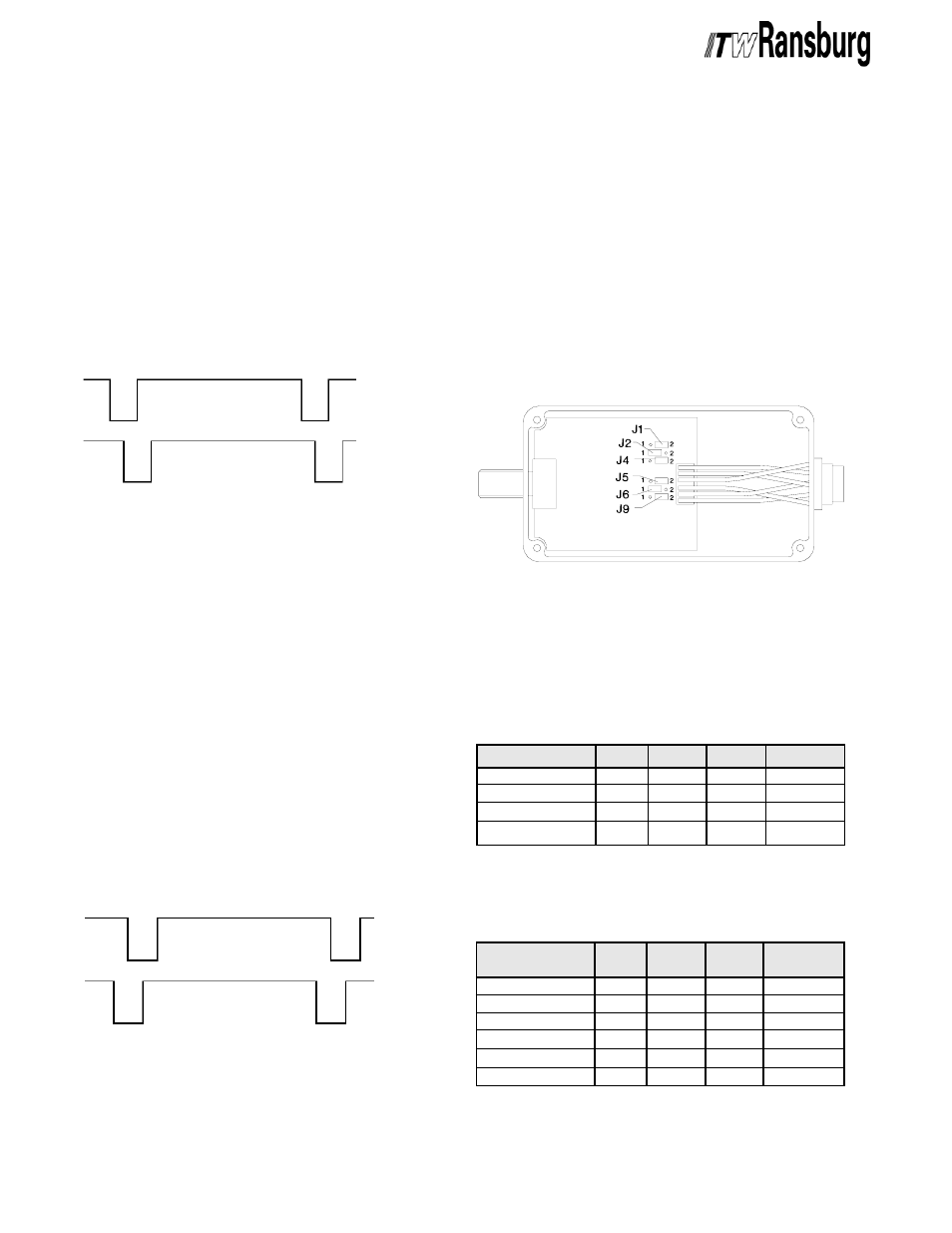
Changing Output Configuration
Changing Output Configuration
Changing Output Configuration
Changing Output Configuration
Changing Output Configuration
Once you have determined the correct output
configuration, programming the receiver is simply
a matter of setting jumpers on the receiver PCB.
Configure the receiver as follows:
1. Remove the four (4) screws that secure the lid
of the receiver enclosure and remove the lid.
2. Locate the six (6) jumpers that control the
output configuration. They are shown in the
following Figure 10.
1 4
1 4
1 4
1 4
1 4
Figure 10: Receiver Output Configuration
Figure 10: Receiver Output Configuration
Figure 10: Receiver Output Configuration
Figure 10: Receiver Output Configuration
Figure 10: Receiver Output Configuration
J u m p e r s
J u m p e r s
J u m p e r s
J u m p e r s
J u m p e r s
Channel B
Reverse Direction
Reverse Direction
Reverse Direction
Reverse Direction
Reverse Direction
Channel A
___
GND
+ Voc
+ Voc
___
GND
Channel B
Forward Direction
Forward Direction
Forward Direction
Forward Direction
Forward Direction
Channel A
OPEN
OPEN
___
CLOSED
___
CLOSED
3. Set the jumpers as shown in Figures 11a and
11b for the desired output configuration.
Figure 1
Figure 1
Figure 1
Figure 1
Figure 11a: Jumper Configuration
1a: Jumper Configuration
1a: Jumper Configuration
1a: Jumper Configuration
1a: Jumper Configuration
*Factory Default Configuration
*Factory Default Configuration
*Factory Default Configuration
*Factory Default Configuration
*Factory Default Configuration
Output Type
Output Type
Output Type
Output Type
Output Type
Open Collector
5V Logic
Vin Logic *
Isolated
J1,5
J1,5
J1,5
J1,5
J1,5
Open
1
2
Open
J2,6
J2,6
J2,6
J2,6
J2,6
1
2
2
1
J4,9
J4,9
J4,9
J4,9
J4,9
2
1
1
Open
Polarity
Polarity
Polarity
Polarity
Polarity
L
H
H
N/A
Figure 1
Figure 1
Figure 1
Figure 1
Figure 11b: Jumper Configuration
1b: Jumper Configuration
1b: Jumper Configuration
1b: Jumper Configuration
1b: Jumper Configuration
*Factory Default Configuration
*Factory Default Configuration
*Factory Default Configuration
*Factory Default Configuration
*Factory Default Configuration
ITW Ransburg
ITW Ransburg
ITW Ransburg
ITW Ransburg
ITW Ransburg
E q u i p m e n t
E q u i p m e n t
E q u i p m e n t
E q u i p m e n t
E q u i p m e n t
AdaptaFlow
Totalizer *
2K 220 *
2K 880 *
E-Z Flow *
DynaFlow
J1,5
J1,5
J1,5
J1,5
J1,5
2
2
2
2
2
2
J2,6
J2,6
J2,6
J2,6
J2,6
1
2
2
2
2
1
J4,9
J4,9
J4,9
J4,9
J4,9
2
1
1
1
1
2
Polarity
Polarity
Polarity
Polarity
Polarity
H
H
H
H
H
H
ARCHIVE