Archive, Receiver output, Rf 1 fiber optic - installation – Ransburg RF1 FiberOptic Meter 77786-XX, A11516-XX User Manual
Page 17: Positive 5 v, Positive vin logic output
FM-00-02.5
1 3
1 3
1 3
1 3
1 3
RF 1 Fiber Optic - Installation
RECEIVER OUTPUT
RECEIVER OUTPUT
RECEIVER OUTPUT
RECEIVER OUTPUT
RECEIVER OUTPUT
CONFIGURA
CONFIGURA
CONFIGURA
CONFIGURA
CONFIGURATION
TION
TION
TION
TION
The receiver can provide its output in any one of
four different formats. The format chosen depends
on the controller to which the receiver is attached.
The receiver outputs signals on two channels,
channel A and channel B. A set of six (6) jumpers
(three for each channel), are used to set the
receiver output format. A description of each output
format is shown as follows:
Positive 5 V
Positive 5 V
Positive 5 V
Positive 5 V
Positive 5 Volt Logic Output
olt Logic Output
olt Logic Output
olt Logic Output
olt Logic Output
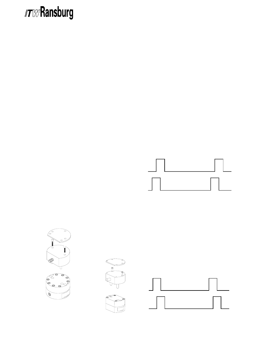
In this output configuration the receiver outputs a
5-Volt logic signal regardless of the input supply
voltage to the receiver. The output signals are
shown in Figure 6.
Figure 5: Mounting the Transmitter to the Meter
Figure 5: Mounting the Transmitter to the Meter
Figure 5: Mounting the Transmitter to the Meter
Figure 5: Mounting the Transmitter to the Meter
Figure 5: Mounting the Transmitter to the Meter
Mount the transmitter to the meter as follows:
1. Inspect the top of the meter and the holes for
the pickups. The top meter surface and pickup
receptacles in the top of the meter must be free of
dirt and debris that would interfere with mounting of
the transmitter or increase the distance between
the pickups and the gears. Clean both of these
areas as required.
2. Inspect the pickups on the transmitter. The
pickup tips are magnetic and will tend to attract
magnetic debris. Any debris that has a t t a c h e d
itself to the pickups must be removed before the
transmitter is mounted on the meter. A small stiff
brush is useful for removing this debris.
3. Remove the three (3) screws that secure the
transmitter cover and remove the cover.
4. Place the transmitter on top of the meter with
the fiber connector oriented towards the fluid
inlet on the meter.
5. Install a #8-32 x 1” socket head cap screw
in each of the transmitter mounting holes. Tighten
these evenly until they are snug.
6. Install the transmitter cover in the reverse
order that it was removed.
High Pressure / Side Inlet
High Pressure / Side Inlet
High Pressure / Side Inlet
High Pressure / Side Inlet
High Pressure / Side Inlet
Low Pressure Bottom Inlet
Low Pressure Bottom Inlet
Low Pressure Bottom Inlet
Low Pressure Bottom Inlet
Low Pressure Bottom Inlet
Figure 6: Mounting the Transmitter to the Meter
Figure 6: Mounting the Transmitter to the Meter
Figure 6: Mounting the Transmitter to the Meter
Figure 6: Mounting the Transmitter to the Meter
Figure 6: Mounting the Transmitter to the Meter
Channel B
Forward Direction
Forward Direction
Forward Direction
Forward Direction
Forward Direction
Channel A
GND
GND
___
+ 5V
___
+ 5V
Application examples of Positive 5 Volt Logic
would be for use with TTL Logic Circuitry.
Positive Vin Logic Output
Positive Vin Logic Output
Positive Vin Logic Output
Positive Vin Logic Output
Positive Vin Logic Output
In this output configuration the receiver outputs a
logic signal that tracks the input supply voltage to
the receiver. The output signals are shown in
Figure 7.
Figure 7: Vin Logic Output
Figure 7: Vin Logic Output
Figure 7: Vin Logic Output
Figure 7: Vin Logic Output
Figure 7: Vin Logic Output
Channel B
Reverse Direction
Reverse Direction
Reverse Direction
Reverse Direction
Reverse Direction
Channel A
GND
GND
___
+ Vin
___
+ Vin
ARCHIVE