Ransburg, Ethernet connector, Interlock connection – Ransburg HV Controller A12311 User Manual
Page 13: Output to cascade, Rs232 connector, Table 1, High voltage controller - installation
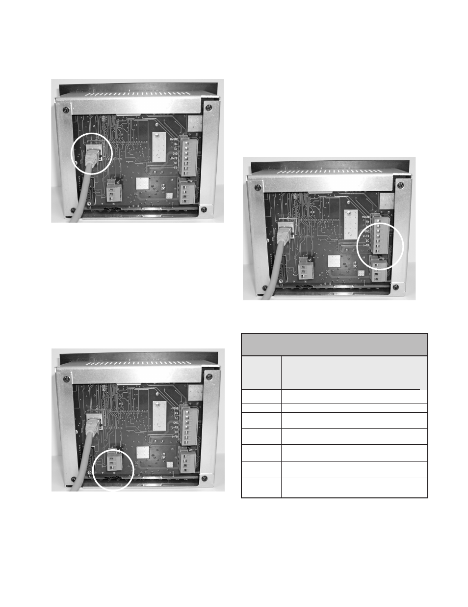
Figure 6: Ethernet Connector
ETHERNET CONNECTOR
Use the appropriate 10/100BASE Ethernet wiring
(Straight EIA/TIA 568A) for your installation us-
ing a RJ-45 plug to connect to the High Voltage
Controller.
INTERLOCK
CONNECTION
Figure 7: Interlock Connection
J9 is supplied to give a hardwire connection thru
relay dry contacts (rated at 24 VDC @ 1 amp
maximum) for when the controller operating power
is turned OFF or a fault condition exists. They
HVC-J6 Cascade
A12295-00 (FRA# EE-4526-800) or
A12296-00 (FRA# EE- 4626-801)
HVGND
Pin 1 OVDC for R+ and E+ Power
R+
Pin 2 Analog DC Cascade Drive Signal
E+
Pin 3 Nominal 15VDC for Cascade
Electronics
GND
Pin 4 0VDC for Analog Cascade Voltage
Feedback
U-FB
Pin 5 Analog Cascade Voltage Feedback
Signal
SC
Pin 6 0VDC for Analog Cascade Current
Feedback
I-FB
Pin 7 Analog Cascade Current
Feedback Signal
TABLE 1
are marked as COM (Common) NC (normally
closed) or NO (normally open) and can be used
by end-user.
OUTPUT TO CASCADE
Make connections from J6 of the controller to, the
cascade per the following table.
Figure 8: Output to Cascade
RS232 CONNECTOR
This connector is a service connection for the
Ransburg factory.
High Voltage Controller - Installation
11
Ransburg
LN-9623-00.1