LumaStream Trinity Power Cord User Manual
Page 9
Document: 66APPMAN-PC Rev: C
20 of 28
11.0
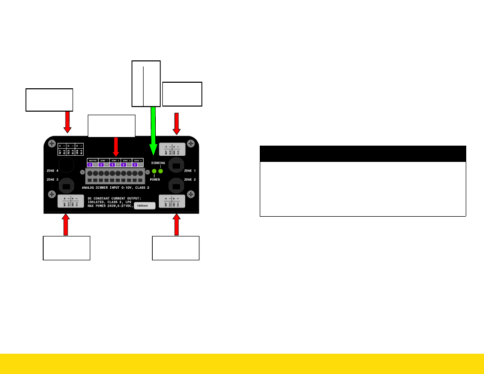
0-10 Vdc ANALOG INTERFACE
11.1 LED Status Indicator
Power Indicator-Green LED will turn off if no power is detected.
Dimming-Green LED will flash when output master is at full on (100%
light intensity). Green LED will vary in intensity proportionally to mas-
ter 0-10 Vdc control signal for intensity levels less than 100%.
Zone #4
Output Channels
10,11,12
Zone #1
Output
Channels 1,2,3
Zone # 3
Output
Channels 7,8,9
Zone #2
Output
Channels 4,5,6
Master & Zone
Dimming Inter-
face Connections
P
ow
e
r I
nd
ic
a
to
r
Ana
log D
im
m
ing
Acti
ve
Document: 66APPMAN-PC Rev: C
9 of 28
5.0
INSTALLATION GUIDELINES AND SAFETY REQUIRE-
MENTS
This power unit has been evaluated to the requirements for:
UL8750 1
st
Edition: LED Light Equipment for Use in Lighting Products
5.1 ELECTRICAL REQUIREMENTS
This power unit is intended for connection to a 20A branch circuit
and an appropriate disconnect device shall be provided as part of
the building installation.
The socket outlet shall be installed near the equipment and shall be
easily accessible.
All secondary output circuits are SELV, limited power source (LPS)
and Class 2.
5.2 MOUNTING AND ENVIRONMENTAL REQUIRE-
MENTS
This power unit is limited to fixed non-plenum locations.
This power unit is rated for dry locations only.
The power unit is intended for use in a nonconductive pollution
environment only.
This power unit is rated for operation at a maximum ambient tem-
perature of 40 ºC.
Allow sufficient spacing around heat sink extrusion fins for convec-
tion air flow.
Do not block ventilation openings.
WARNING
RISK OF FIRE OR ELECTRIC SHOCK:
Do not modify, remove, or replace the input power cord
Do not remove enclosure cover. No serviceable parts inside
Do not connect Analog Interface to class 1 circuits
Follow all NEC/CEC, local electrical code requirements for installation
To reduce the risk of fire or electric shock, do not interconnect output
terminations