LumaStream Trinity Power Cord User Manual
Page 11
Document: 66APPMAN-PC Rev: C
18 of 28
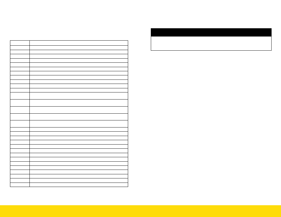
10.7 STANDALONE TEST MODES
Test modes are specified by address location and may be used to
debug network connections or provide standalone color changing
options without the need for a DMX controller. Colours are assuming
LED loads are connected in RGB configuration as shown on page 15,
section 9.4)
ADDRESS
FUNCTION/SEQUENCE
000
NO FUNCTION
001-512
DMX ADDRESS MODE
513
GREEN ON
514
RED ON
515
BLUE ON
516
BLUE & RED ON (MAGENTA)
517
BLUE & GREEN ON (CYAN)
518
GREEN & RED ON (YELLOW)
519
ALL OUTPUTS AT 5%
520
EACH COLOR RAMPING UP AND DOWN INDIVIDUALLY – SPEED 1
521
EACH COLOR RAMPING UP AND DOWN INDIVIDUALLY – SPEED 2
522
CROSS FADE BETWEEN COLOURS (RED UP, GREEN UP, RED
DOWN, BLUE UP ETC.) – SPEED 1
523
CROSS FADE BETWEEN COLOURS (RED UP, GREEN UP, RED
DOWN, BLUE UP ETC.) – SPEED 2
524
CROSS FADE BETWEEN COLOURS (RED UP, GREEN UP, RED
DOWN, BLUE UP ETC.) – SPEED 3
525
CROSS FADE BETWEEN COLOURS (RED UP, GREEN UP, RED
DOWN, BLUE UP ETC.) – SPEED 4
526
CROSS FADE BETWEEN COLOURS (RED UP, GREEN UP, RED
DOWN, BLUE UP ETC.) – SPEED 5
530
ALL ON
531
CHANNEL 1 ON
532
CHANNEL 2 ON
533
CHANNEL 3 ON
534
CHANNEL 4 ON
535
CHANNEL 5 ON
536
CHANNEL 6 ON
537
CHANNEL 7 ON
538
CHANNEL 8 ON
539
CHANNEL 9 ON
540
CHANNEL 10 ON
541
CHANNEL 11 ON
542
CHANNEL 12 ON
Document: 66APPMAN-PC Rev: C
11 of 28
8.0 OUTPUT CHANNEL REQUIREMENTS
8.1 Electrical Output Specifications:
Output specifications are defined in table 2 on page 4 of this manual.
Actual output currents and maximum voltages are dependant on the
model configuration, see table 6, 8 or table 10 at the beginning of this
manual for configuration options.
8.2 Output Wiring Requirements
WARNING: All output channels are isolated from each other and
require a separate 2 wire twisted pair for each output LED load.
When connecting LED loads to output cables observe ‘+’ and ‘-‘ po-
larity connections to prevent damage to loads. To reduce risk of fire or
electric shock, do not interconnect output terminations.
A common anode or cathode wiring method for multiple LED
loads cannot be used for the TRINITY PC.
All output wires should be connected to their respective LED loads
before power up to prevent inadvertent shorting of outputs. Shorting of
outputs (+ve to –ve only) will result in a hiccup mode of operation with
automatic recovery after removal of a short.
Output Class 2 circuit wiring must comply with NEC Article 725 wir-
ing methods or to CEC section 16-210 wiring methods.
Output cabling should be overall shielded cables with twisted pair
conductors (18 AWG ) to minimize cross talk between channels and mini-
mize Electromagnetic Interference (EMI).
Consult your local Electrical Safety Authority for acceptability in
your end use application.
With appropriate cabling, the TRINITY PC may be remote mounted
up to 150 feet (45 meters) from the LED loads.
7.0 INPUT REQUIREMENTS
7.1 Electrical Input Specifications:
Input specifications are defined in table 1 on page 4 of this
CAUTION
RISK OF DAMAGE:
DO NOT connect input of power unit to a phase cut dimmer or dim-
ming panel. It will cause internal damage to the power unit