LumaStream Trinity Power Cord User Manual
Page 2
Document: 66APPMAN-PC Rev: C
2 of 28
CONTENTS
1.0
MECHANICAL DIMENSIONS & SPECIFICATIONS ...................................... 3
1.1
SPECIFICATIONS………………………………………………………4
2.0 SCOPE ............................................................................................................................... 8
3.0 OWNER RESPONSIBILITIES .................................................................................. 8
4.0 EMC COMPLIANCE ..................................................................................................... 8
5.0 INSTALLATION GUIDELINES AND SAFETY REQUIREMENTS ........... 9
5.1
Electrical Requirements ............................................................................................ 9
5.2
Mounting and Environmental Requirements ................................................. 9
6.0 MOUNTING ORIENTATION ................................................................................. 10
7.0 INPUT REQUIREMENTS ........................................................................................... 11
8.0 OUTPUT CHANNEL REQUIREMENTS .............................................................. 11
8.1
Electrical Output Specifications ........................................................................... 11
8.2
Output Wiring Requirements ............................................................................... 11
8.3
Output Voltage Dynamic Range ....................................................................... 12
8.4 Number of Output LED`s Per Channel Calculation Example ............. 12
9.0 DIMMING CONTROL OPTIONS ...........................................................................13
10.0 DMX INTERFACE ........................................................................................................13
10.1 DMX Typical Wiring Diagram ...............................................................................13
10.2 DMX LED Status Indicator .................................................................................... 14
10.3 DMX Interface Connections ...................................................................................15
10.4 DMX Cabling ................................................................................................................. 16
10.5 DMX Addressing and Termination Requirements .................................... 16
10.6 Output Channel Connections and DMX Mapping Table ........................ 17
10.7 Standalone Test Modes .......................................................................................... 18
10.8 Multi Channel Control Modes ............................................................................... 19
11.0 0-10V ANALOG INTERFACE ................................................................................ 20
11.1
LED Status Indicator ............................................................................................... 20
11.2 Output Zone/Channel Connection Table ....................................................... 21
11.3 Analog Interface Specefications ........................................................................22
11.4 Analog Interface Cabling and Connections .................................................22
11.5 Typical Wiring Diagram ......................................................................................... 23
11.6 Installation Examples .............................................................................................. 24
12.0 0-10V MULTI-ZONE ANALOG INTERFACE..................................................27
12.1 LED Status Indicator ................................................................................................27
12.2 Output Zone/Channel Connection Table ..................................................... 28
12.3 Multi-Zone Analog Interface Specefications .............................................. 28
Document: 66APPMAN-PC Rev: C
27 of 28
12.0
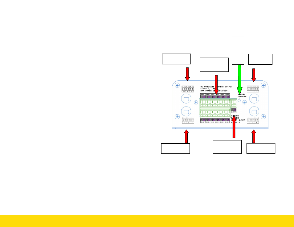
0-10 Vdc MULTI-ZONE ANALOG INTERFACE
12.1 LED Status Indicator
Analog Dimming Indicator-Green LED will be in one of the following
states when the unit is powered:
Flashing Fast - Master Dimming input is at full On (100%)
Flashing Slow - Master Dimming input fully dimmed (0%)
Steady State - Green LED will vary in intensity proportionally to
master 0-10 Vdc control signal for intensity levels between 0%
and 100%.
Zone 10, 11, 12
Output
Zone 1,2,3
Output
Zone 7,8,9
Output
Zone 4,5,6
Output
Zone
Dimming Inter-
face Connections
Ana
log D
im
m
ing
Ind
ic
a
to
r
Master Dimming
Interface
Connection