Kasco Marine LE375 User Manual
Page 4
4
Kasco Quick Disconnect 50 Hz Size Chart:
Gland
O.D. of Cord
Grey
7-9mm
White
9-11mm
Black
11-13mm
Yellow
13-15mm
Kasco 50 Hz Equipment Wire Size Chart
Model
Cord Length
10m
30m
60m
LE275
1.5mm
2
1.5mm
2
1.5mm
2
LE375
1.5mm
2
1.5mm
2
1.5mm
2
Parts Included
LE275
A. Light Kit with stub cord (1)
•
B. 75-watt, 12-volt, MR-16 Halogen Bulbs,
•
installed in fi xtures (2)
C. 1/4” x 1” Stainless Steel Bolts (2)
•
D. 1/4” Stainless Steel Flat Washer (2)
•
E. 1/4” Stainless Steel Lock Washer (2)
•
F. 1/4” Stainless Steel Nut (2)
•
G. Nylon Cable Tie
•
H. Optional Colored Bulbs
•
I. Quick Disconnect, Strain relief, gland pack,
•
and potting kit
Note: Extra hardware may be included.
LE375
A. Light Kit with stub cord (1)
•
B. 75-watt, 12-volt, MR-16 Halogen Bulbs,
•
installed in fi xtures (3)
C. 1/4” x 3/4” Stainless Steel Bolts (3)
•
D. 1/4” Stainless Steel Flat Washer (3)
•
E. 1/4” Stainless Steel Lock Washer (3)
•
F. 1/4” Stainless Steel Nut (3)
•
G. Nylon Cable Tie
•
H. Optional Colored Bulbs
•
I. Quick Disconnect, Strain relief, gland pack,
•
and potting kit
Note: Extra hardware may be included.
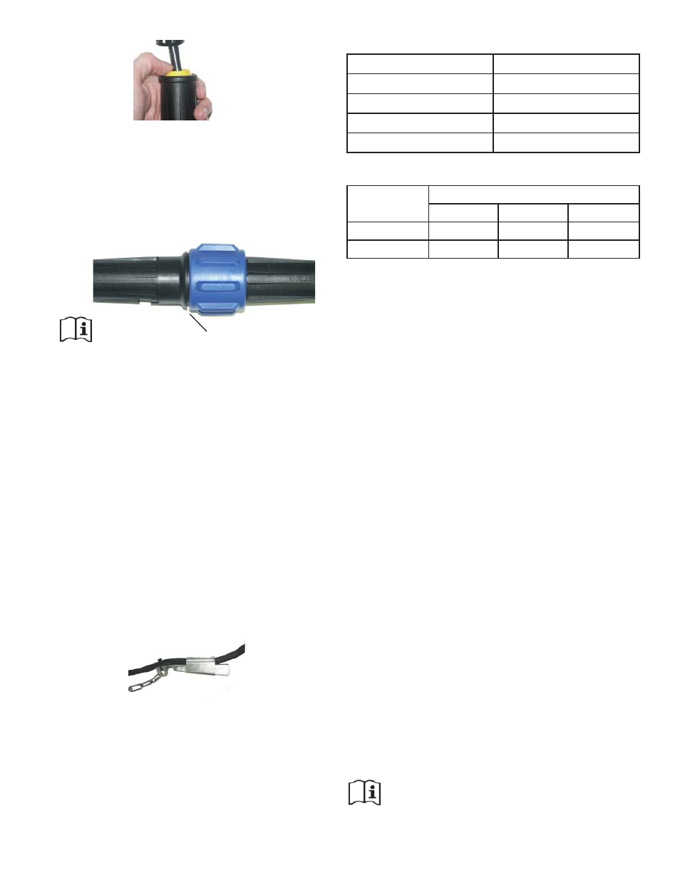
STEP SEVEN
Once the two subassemblies have been completed,
they can be joined together. Plug pin assembly into
the socket assembly and tighten the large blue nut
securely. The blue nut should be hand tightened only.
(See fi gure below).
Note: There is a small gap after tightening
For seasonal removal, your quick disconnect includes
an optional water tight cover. Simply separate the
quick disconnect and insert the sealing cover into the
large blue nut half and tighten fi rmly.
Strain Relief
The Strain Relief must be installed to protect the
Quick Disconnect from damage due to excessive
strain. The Strain Relief should be installed on the
user supplied cord length (not on the Kasco supplied
stub cord). It should be position about 15cm from the
Quick Disconnect. To install, insert the narrow end of
the elongated clamp with the chain connected into the
wide end of the short clamp. Use a rubber mallet to
tap the two pieces together securely. A Nylon Tie can
be used to keep it attached to the cord. The chain can
then be attached to the fl oat.
Wire Sizing & Gland Sizing
The chart below shows the proper Gland to be used
with different cord sizes. The measurements are based
on the Outside Diameter (O.D.) of the cord. Smooth,
round cords should be used.