Kasco Marine J Series User Manual
Page 4
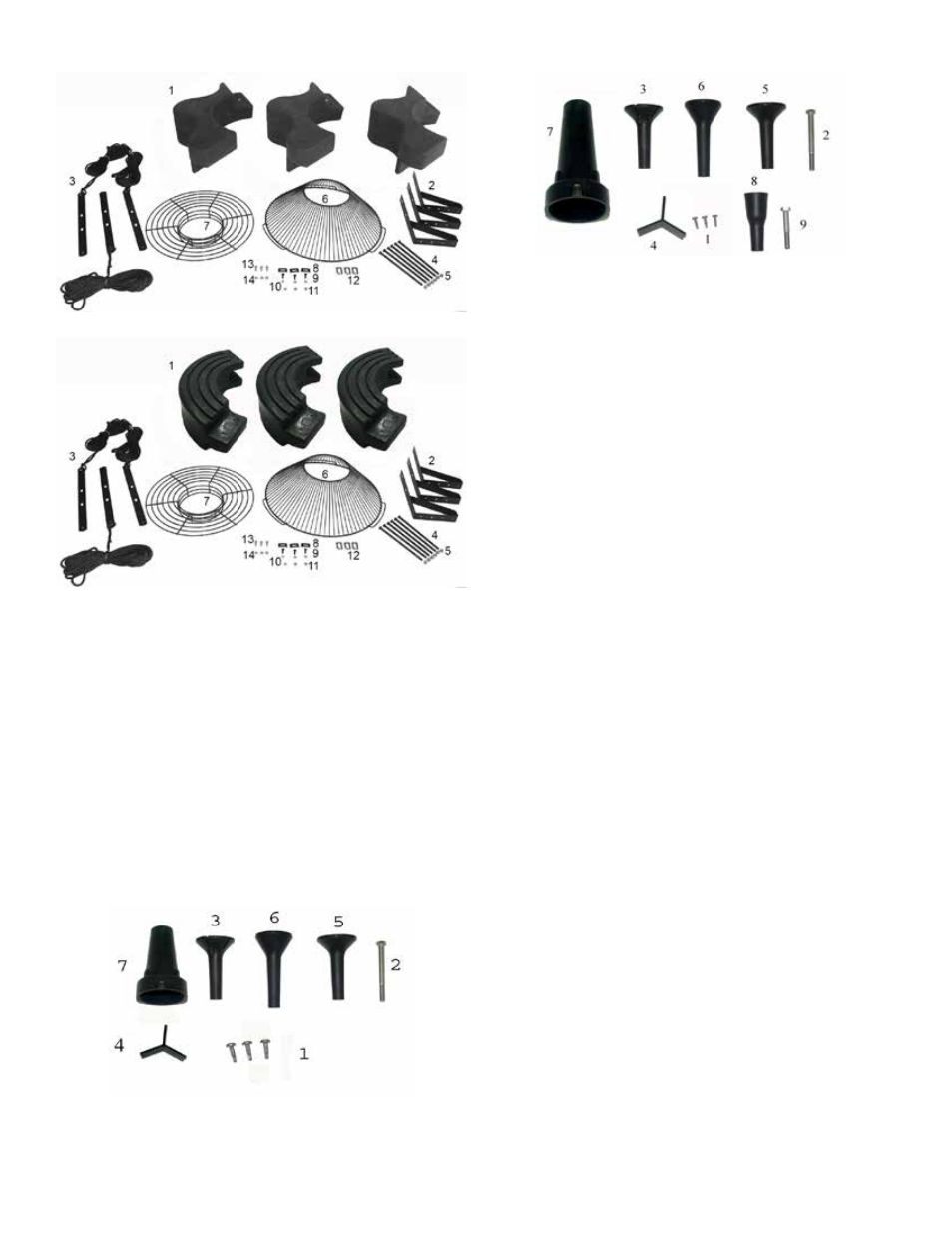
5.1JF, 5.3JF Nozzle Diagram
7.3JF Nozzles include linden and sequoia.
NOTE: Extra hardware may be included.
Tools & Supplies Needed
• Anchors or stakes for installing unit (3)
• Philips head screw driver for mounting C-85
• Electrical Supply near pond on a post with room
for mounting the control panel
• Three 12” galvanized pipe for weighting ropes
(optional)
• #10 x 1” long or longer screw(s) for mounting the
control panel (4)
• 7/16” Socket & Wrench (1)
• 7/16” Wrench (1)
• 9/16” Socket & Wrench (1)
• 9/16” Wrench or adjustable crescent wrench (1)
• Flat head screw driver (1)
Assembly Instructions
STEP ONE
Remove all contents from package and place on a
clean, flat surface. Inspect the shipment for any dam-
ages. If damages are found, immediately notify your
carrier and your Kasco Marine, Inc. representative.
Next, cross reference the parts included in the ship-
ment with the Parts Included sheet in this manual.
Make sure you have all the parts needed. If any
shortages are found, contact your Kasco representative
immediately.
STEP TWO
Arrange the three Float Sections (Part #B1) upright
(plug on bottom) so the overlap of one section aligns
with the next section and loosely push the three sec-
tions together to form a continuous ring.
8400JF, 3.1JF, 2.3JF, 3.3JF
8400JF, 3.1JF, 2.3JF, 3.3JF parts diagram
5.1JF, 5.3JF, 7.3JF parts diagram
Control Panel in separate box (1) (if purchased)
Set of Interchangeable Nozzles (5) (Diagrams)
1. #6 x 1/2” Ph Pan Head Self Tap Screw (3)
2. 3/8” x 4” bolt (1)
3. Linden Nozzle (1)
4. Redwood Y Insert (installed in #7)(1)
5. Juniper Nozzle (1)
6. Willow Nozzle (1)
7. Redwood & Spruce Nozzle (1)
8. Sequoia Nozzle
9. 3/8” x 2.5” Bolt (1)
8400JF, 3.1JF, 2.3JF, 3.3JF Nozzle Diagram