Setup instructions – General Tools and Instruments DPS16 User Manual
Page 8
8
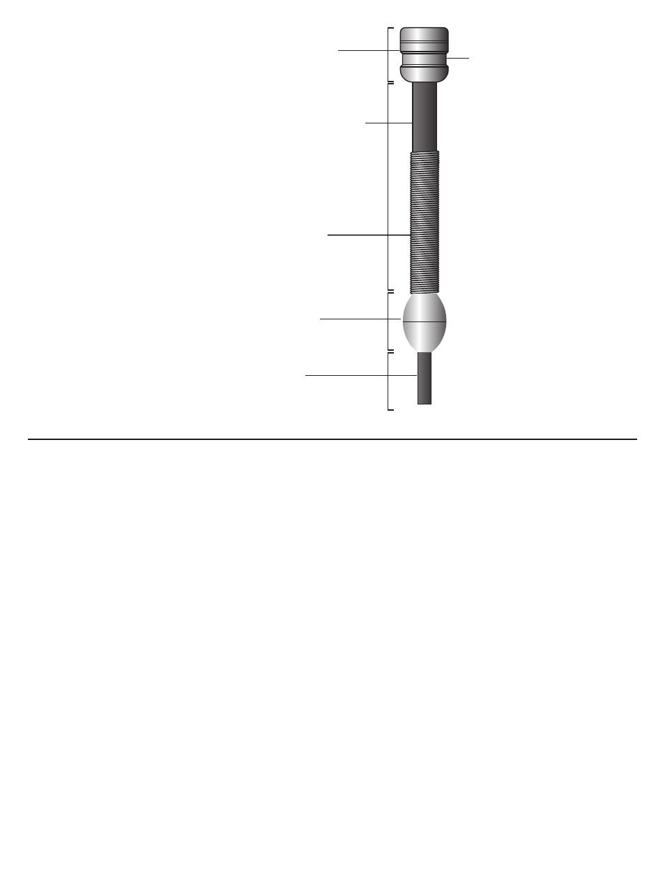
Fig. 3. Structures near the
camera-tipped
end of the probe
SETUP INSTRUCTIONS
ATTACH PROBE TO CONSOLE
Attach the P16PIP to the H16 by 1) inserting the H16 into the bracket at the top of the P16PIP
and 2) plugging the P16PIP’s probe connector (see bottom of Fig. 2) into the connector at the top
of the console (Fig. 1, Callout 14). The connectors mate in only one way, when the two red dots—
one on the console’s connector and the other under the collar at the end of the probe—are
aligned. After you have lined up the dots, push the two connectors together so the alignment keys
on opposite sides of the probe’s connector slide over the flats of the console’s connector. Slide
the collar on the probe’s connector forward and tighten the collar by turning it clockwise.
You can now remove the protective rubber cap from the camera-tipped end of the probe. It is
good practice to replace the cap whenever the probe will not be used for a while. Now is also the
time to peel away the plastic film that protects the console’s LCD.
To disconnect the probe from the console, turn the collar counterclockwise and pull the probe
straight out and away.
CHARGE CONSOLE BATTERY
To power on for the first time, plug one end of the supplied AC adapter/battery charger into a
wall socket. Then swing the black rubber protective flap away from the right side of the H16 to
expose the AC adapter jack (Fig. 1, Callout 10). Insert the cylindrical plug at the end of the
adapter/charger cable into the AC adapter jack. This will begin charging the console’s battery.
Camera head
Rubber probe cover
Joint ball
Probe
Accessory mounting ring
Metal coil
spring sleeve