Finish Thompson DB 11/15 Series User Manual
Page 7
7
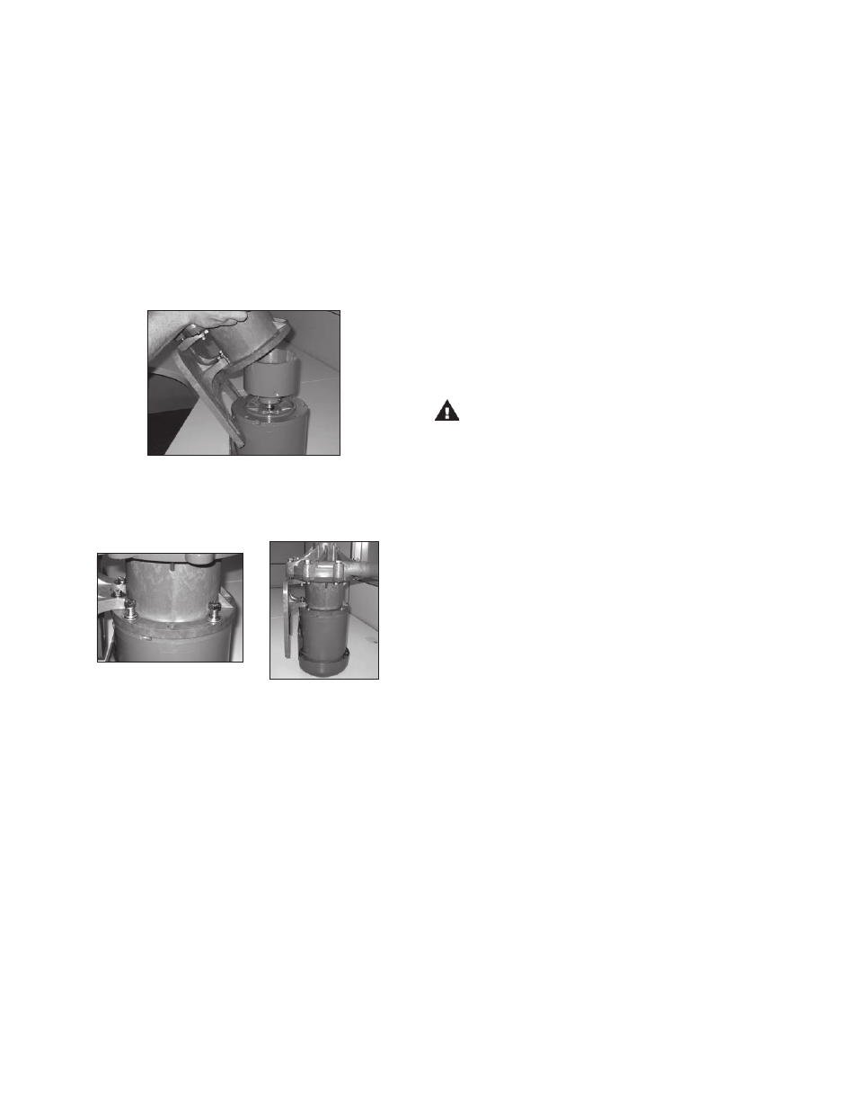
Tip the pump end at an angle (discharge is approximately
45º) so that it is just touching the edge of the outer
drive magnet assembly. See figure 8.
8. Secure the pump to the motor with (4) 3/8” bolts, lock washers
and flat washers (items 15,16,17). See figures 9 and 10.
NOTE: Apply anti-seize compound on threads of bolts.
Section II - Installation
Mounting
Pump foot should be securely fastened to a solid foundation.
If the pump was received with plastic shipping shims, these
shims may be used as additional support for the motor feet
(though not required).
Piping
CAUTION: The NPSH available to the pump must be
greater than the NPSH required. Filters, strainers and any
other fittings in the suction line will lower the NPSH avail
able and should be calculated into the application.
•
Install the pump as close to the suction source as
possible.
•
Support the piping independently near the pump to elimi-
nate any strain on the pump casing. Also, the piping should
be aligned to avoid placing stress on the pump casing.
•
The suction side of the pump should be as straight and
short as possible to minimize pipe friction.
•
Keep bends and valves at least ten pipe diameters away
from the suction and discharge.
•
The suction line should be at least as large as the suction
inlet port or one pipe size larger so that it does not affect
the NPSHa. Do not reduce the suction line size.
•
The suction line should not have any high spots. This can
create air pockets. The suction piping should be level or
slope slightly upward to the pump.
•
A check valve and control valve (if used) should be
installed on the discharge line. The control valve is used
for regulating flow. An isolation valves on the suction and
discharge are used to make the pump accessible for
maintenance. The check valve helps prevent the pump
against damage from water hammer. This is particularly
important when the static discharge head is high.
•
If flexible hose is preferred, use a reinforced hose rated
for the proper temperature, pressure and chemical
resistance against the fluid being pumped.
•
The suction valve must be completely open to avoid
restricting the suction flow.
Figure 8
Figure 9
Figure 10
Carefully lower the pump onto the drive magnet assembly
by tipping discharge forward to 90º and dropping straight
down. The last 3-4 inches (8-10 cm) before the pump
reaches the motor will have STRONG magnetic attraction
between the pump and outer drive magnet assembly.
9. Rotate the motor fan to ensure there is no binding in the
pump.
10. Proceed to Installation Section
For NEMA 184 and IEC 80, 90, 100, 112-B14 frame pumps:
NOTE: B5 motors with clearance holes will require customer
supplied hardware. B5 pumps with 100/112 frame do not in-
clude a pump foot.
Pumps shipped without motors in the above referenced frame
sizes are shipped with the pump foot (item 11) uninstalled
to allow the motor to be connected to the pump.
The pump foot will be installed after the pump has been at-
tached to the motor. Follow pump mounting instructions from
#7 above. Proceed to the foot installation instructions below.
Foot Installation:
(1) Place the pump and motor in an upright position on the
motor fan shroud.
(2) Install the plastic foot (item 11) on to the motor adapter
(item 8D). Use the longer M6 bolts, lock washers and flat
washers (items 24A, 25, and 26) for the front bolt holes
towards the clamp ring. See figure 34 on page 10.
` (3) Use the shorter M6 bolts, lock washers and flat washers
(items 24, 25 and 26) for the rear bolt holes towards the
motor face. Note: Nuts (item 30) are glued into the rear
the motor adapter to help with the installation of the rear
bolts. Make sure the nuts are still in place. See figure 35
on page 10. Tighten bolts to 5 ft-lbs.
Install the pump end on the motor/drive magnet assembly. With
the motor facing upright, align the pump feet so that the
motor feet and pump feet are on the same side.