Finish Thompson DB 11/15 Series User Manual
Page 12
12
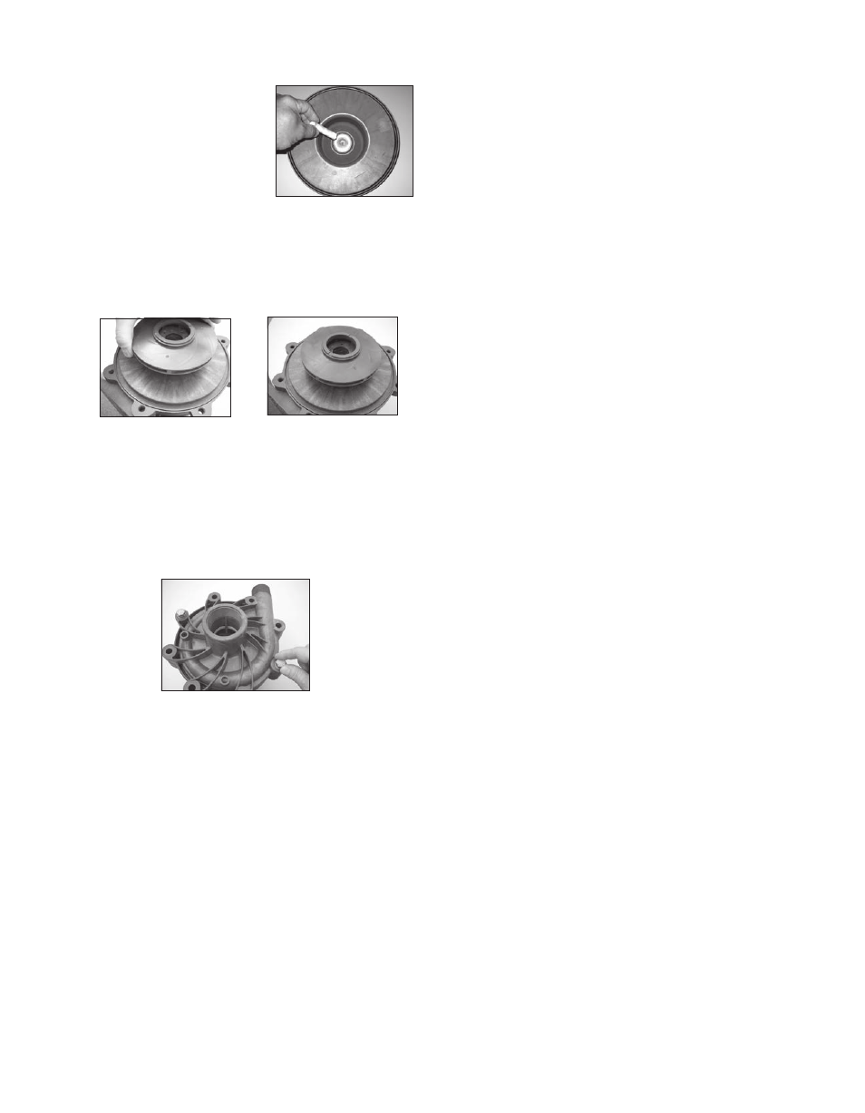
7. Install o-ring (item 2). See figure
39.
8. Install impeller shaft (item 6) into
barrier by aligning the flats
on the shaft with the ones in
the barrier. Make sure it is
completely seated. See figure 39.
9. Carefully install the impeller/inner drive assembly (items 4,
4A, 5, 5A) by sliding it over the impeller shaft in the barrier. It is
Figure 39
normal for the impeller /inner drive to pop up a slight amount
due to magnetic forces. See figures 40 and 41.
Figure 40
Figure 41
10. Install the impeller housing (item 1). Make sure the dis
charge is in the correct orientation in relation to pump foot.
Align the shaft in the barrier with the front shaft support in
the impeller housing. Press down to push the impeller/in
ner drive magnet assembly into position. Holding the
impeller housing with one hand, install and finger-tighten
two bolts, lock washers and flat washers (items 12, 13, 14)
in opposite locations. See figure 42.
Figure 42
11. Install the remaining bolts, lock washers and flat washers
finger tight.
12. Tighten all the bolts evenly using a star pattern. Tighten to
20 foot-lbs (27 N-m).
13. Reinstall the pump on the motor/drive magnet following
instructions found in “Assembly, Pumps Without Motors,”
steps 7-10.