Wiring diagrams – Fire Fighting Enterprises FIRERAY 3000 User Manual
Page 3
3
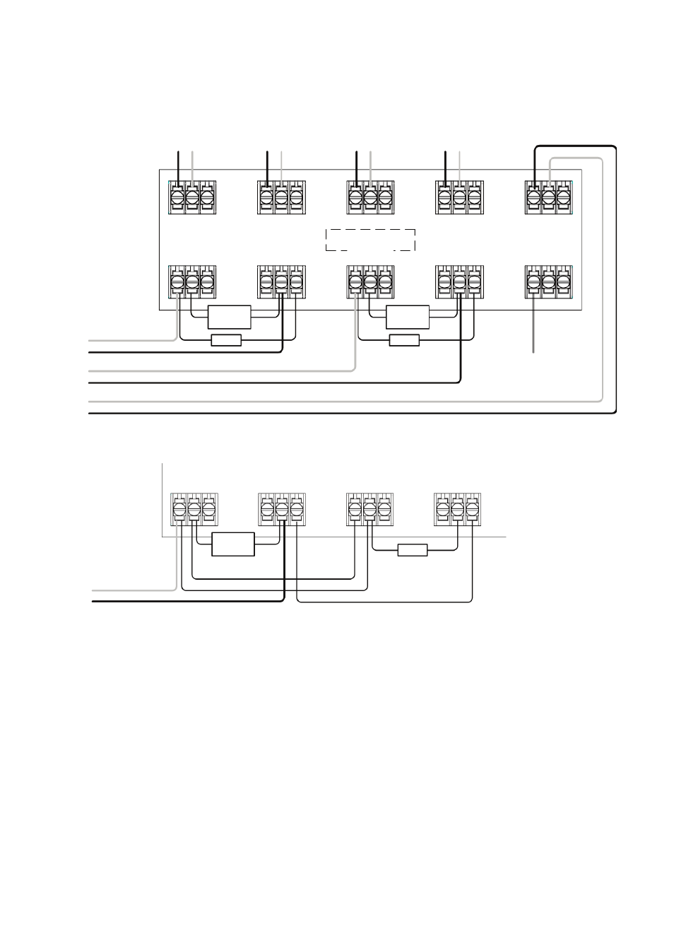
• Note 1: This component is the fire resistor. Its value is specified by the Fire Control Panel
manufacturer. For U.S. installations it is typically a short circuit
• ALWAYS use a separate 2-core cable for each Receiver head
• CAUTION: For system monitoring - Do not use looped wire under any terminals. Break wire
run to provide monitoring of connections
• Components not supplied:
• End Of Line ('EOL') component - supplied by Fire Control Panel manufacturer
• Fire Resistor
• After installation, check operation of Fire and Fault connection on Fire Panel
• Apply a voltage of 5V to 40V to ‘EXT RST’ contact for at least 2 seconds to clear a latched
fire condition
• For wiring to other types of Fire Control Panel, or to wire multiple Controllers onto one Zone,
refer to additional installation instructions supplied with the product
2. Wiring Diagrams
RECEIVER 1
OUTPUT
+ -
RECEIVER 2
OUTPUT
+ -
TRANSMITTER
SUPPLY
+ -
TRANSMITTER
SUPPLY
+ -
12V to 36V DC
RECEIVER 1
FIRE
N/O COM N/C
RECEIVER 1
FAULT
N/O COM N/C
RECEIVER 2
FIRE
N/O COM N/C
RECEIVER 2
FAULT
N/O COM N/C
RECEIVER 1
FIRE
N/O COM N/C
RECEIVER 1
FAULT
N/O COM N/C
RECEIVER 2
FIRE
N/O COM N/C
RECEIVER 2
FAULT
N/O COM N/C
see note 1
see note 1
EOL
EOL
see note 1
EOL
EXTERNAL
RESET
EXT
RST
ZONE 1 -
ZONE 1 +
ZONE 2 -
ZONE 2 +
SUPPLY -
SUPPLY +
ZONE 1 -
ZONE 1 +
For connection of two Receivers to one zone:
Wiring two Receivers onto two zones: