0 connecting meters to the idr, E-mon d-mon meter connections, Pulse output meters (idr-st models only) – E-Mon EIDR-16J*RJ User Manual
Page 8
INTERVAL DATA RECORDER (IDR)
62-0394-03
8
3.0 CONNECTING METERS TO THE IDR
E-Mon D-Mon Meter Connections
a. Each E-Mon D-Mon meter has two modular jacks located at the top of the
main circuit board. The jack on the left (RJ-45, 8-pin) is used to connect the
meter to the IDR.**
NEVER USE 6-PIN JACKS LABELED “PORT 0” OR “PORT 2” TO CON-
NECT A METER TO THE IDR.
b. * All E-Mon D-Mon meters must be connected to meter jacks #1-8 using 6-
conductor flat modular cable.**
c. *IDR-16 - If the IDR is an IDR-16, connect the additional meters to Jacks #9-
16 on the circuit board using 6-conductor flat modular cable.**
d. IDR-8s supplied with plug-in screw type connectors can be up to 500 feet
from all meters, and utilize a pair of wires for connecting to the meter pulse
output.**
* See Appendix D for item B&C above.**
** For more information on cable assembly, see Appendix B.**
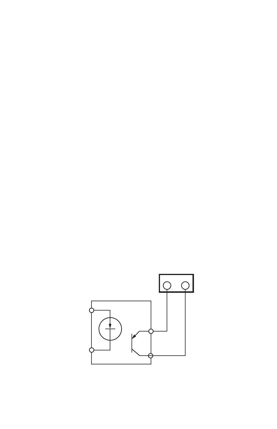
Pulse Output Meters (IDR-ST Models Only):
a. Each meter is interfaced with the IDR through the plug-in screw type connec-
tors. Any of the connectors may be used with #22-14 AWG conductors.
b. When used with solid-state switches, correct polarity must be observed in
order for that contact to be recognized. The left terminal of the screw-termi-
nal on the IDR must be connected to the plus (+) side of the switch.
Fig. 4. Meter Connections.
c. The meter can be up to 500 feet away from the IDR.
+
–
COM SIG
M33472A
IDR TERMINAL
SOLID
STATE
SWITCH