5 line voltage/current sensor diagnostics – E-Mon E20-6003200J-G-KIT User Manual
Page 14
GREEN CLASS METER
62-0415-01
14
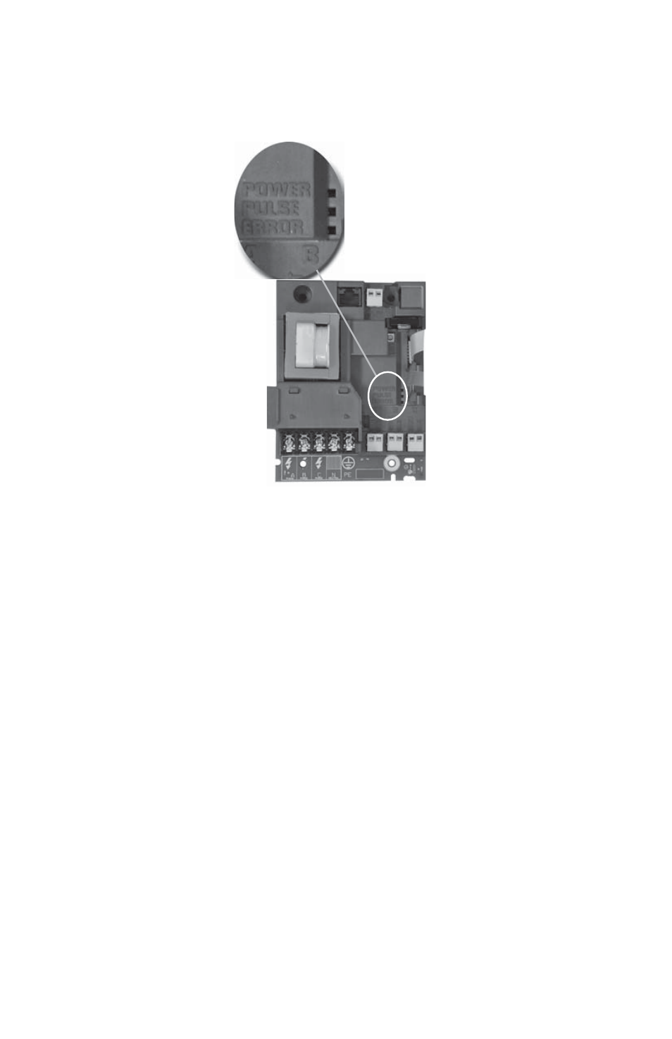
4.5 Line Voltage/Current Sensor Diagnostics
Fig. 8. Main Board
The three-phase AC MAINS voltage wiring and the current sensor wiring must be
connected in the proper phase sequence. If there is a phase sequence error, the
display LCD will display a message ‘Check Sensor” in the upper right hand corner.
Additionally, LED D1, Check Sensor, will illuminate if there is a phasing error.
Verify that the AC MAINS voltage wires are all connected to the correct positions on
terminal block. Inspect the MAINS input wiring to verify each conductor is terminated
at the correct terminal block position. Using an AC voltmeter, measure the AC voltage
for each phase to neutral terminal and to the frame ground point.
M33181
This manual is related to the following products:
- E20-6001600J-G-KIT E20-600800-J-G-KIT E20-600400-J-G-KIT E20-600200-J-G-KIT E20-600100-J-G-KIT E20-4803200J-G-KIT E20-4801600J-G-KIT E20-480800-J-G-KIT E20-480400-J-G-KIT E20-480200-J-G-KIT E20-480100-J-G-KIT E20-2083200J-G-KIT E20-2081600J-G-KIT E20-208800-J-G-KIT E20-208400-J-G-KIT E20-208200-J-G-KIT E20-208100-J-G-KIT