3 current sensor wiring – E-Mon E20-6003200J-G-KIT User Manual
Page 12
GREEN CLASS METER
62-0415-01
12
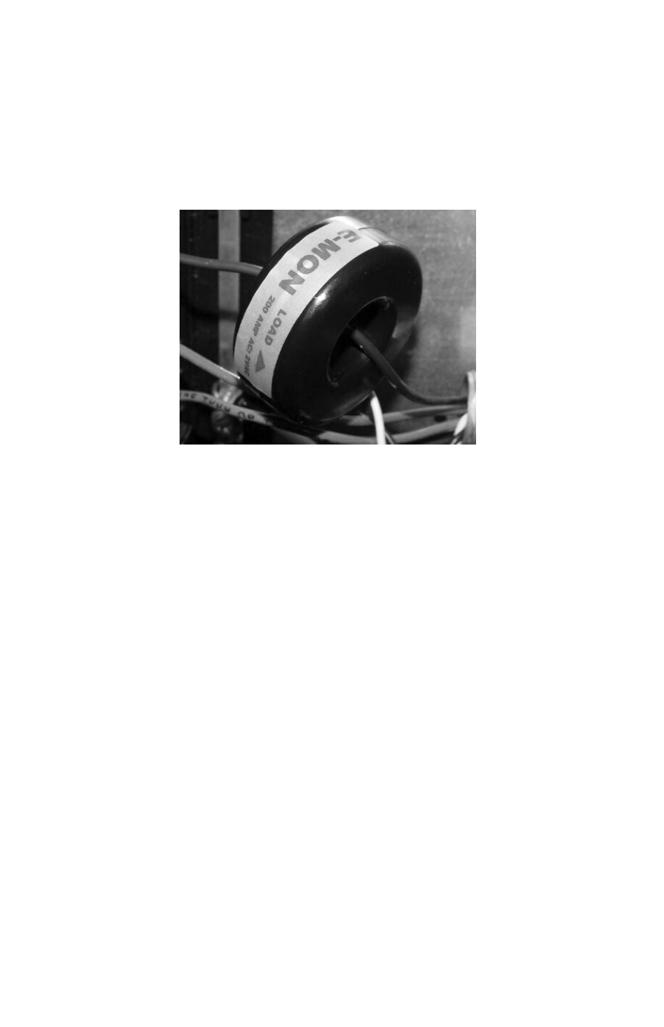
With the power off, disconnect the conductor from its breaker or terminal. Slide the
solid-core current sensor over the conductor, making sure that the indicator on the
sensor is pointing in the direction of the load. After this is done, reconnect the
conductor and verify that it is properly installed.
Run the black and white wires from the solid-core current sensors and install them
according to the standard installation diagram. When this is completed, the power to
the monitored conductor can be turned back on.
Fig. 5. Solid-core Current Sensor
4.3.3 Current Sensor Wiring
Once all the current sensors are installed on their appropriate phase conductors, you
can begin terminating the current sensors on to the Green Class main power board.
The current sensor leads can be extended up to 2,000 feet (using #14-22 AWG wire)
for remote monitoring applications. Consult your local electrical codes for proper wire
sizing (#22 AWG twisted pair wire with a black and white conductor, rated for 600 VAC
recommended.)
The current sensor connection points are located on the bottom right of the main
power board. Three removable plugs exist, one for each current sensor phase input.
The header portions of the connectors are labeled A, B and C. Text on the plastic cover
of each of the connectors instruct you which terminal of the plug is for the white
conductor and which terminal is wired to the black conductor. Once each current
sensor is wired to its respective plug, insert each plug into the appropriate header.
- E20-6001600J-G-KIT E20-600800-J-G-KIT E20-600400-J-G-KIT E20-600200-J-G-KIT E20-600100-J-G-KIT E20-4803200J-G-KIT E20-4801600J-G-KIT E20-480800-J-G-KIT E20-480400-J-G-KIT E20-480200-J-G-KIT E20-480100-J-G-KIT E20-2083200J-G-KIT E20-2081600J-G-KIT E20-208800-J-G-KIT E20-208400-J-G-KIT E20-208200-J-G-KIT E20-208100-J-G-KIT