8 line voltage/current sensor diagnostics – E-Mon E10-2277200JKIT User Manual
Page 16
CLASS 1000 METER
62-0388-01
16
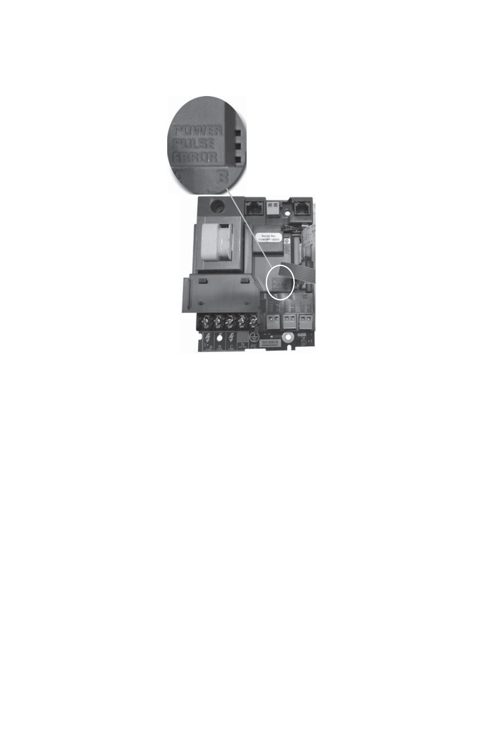
4.8 Line Voltage/Current Sensor Diagnostics
Fig. 8. Main Board Configuration
If the meter is not correctly wired, the “ERROR” indicator will be on.
Verify that the AC MAINS voltage wires are all connected to the correct positions on
the terminal block. Inspect the MAINS input wiring to verify each conductor is
terminated at the correct terminal block position. Using an AC voltmeter, measure the
AC voltage for each Phase to Neutral terminal and to the Frame ground point.
Verify each current sensor by running at least 1% of the full scale rated current through
the conductor being monitored by each phase. (e.g. 2 amp load required for each
phase to perform sensor diagnostic procedures.)
M33181
This manual is related to the following products: