E-Mon E10-2277200JKIT User Manual
Page 10
CLASS 1000 METER
62-0388-01
10
After all conductors are connected to their respective terminal block positions and
tightened down, verify that each terminal block screw is securely fastened by gently
tugging on each conductor. Verify that no conductor wires are frayed or are shorting to
adjacent terminal block positions.
STEP 5: External Switch Mechanism/In-Line Fuse Installation.
To ensure a safe installation, the Class 1000 meter requires an external switch
mechanism, such as a circuit breaker, be installed on the Class 1000 MAINS input
wiring. The switch mechanism must be installed in close proximity to the meter and
easily reachable for the operator. This device must also be marked as the
disconnecting device for the Class 1000 meter.
Install 1/10 Amp Slow Activation in line fuses with the suitable voltage rating for each
conductor phase at the MAINS input to the meter. The fuses must be labeled to
indicate voltage and current rating as well as element characteristics. The fuse
element must be slow activating type.
STEP 6: Once the MAINS wiring is complete, replace the clear lexan protective shield
over terminal block TB1 and close the enclosure front panel. Secure the enclosure
cover using the locking mechanism. Activate the external circuit breaker or equivalent
switch to apply AC MAINS power to the unit.
The Class 1000 meter display should turn on and indicate total kWh accumulation
reading and KW load. The display will cycle between the two readings.
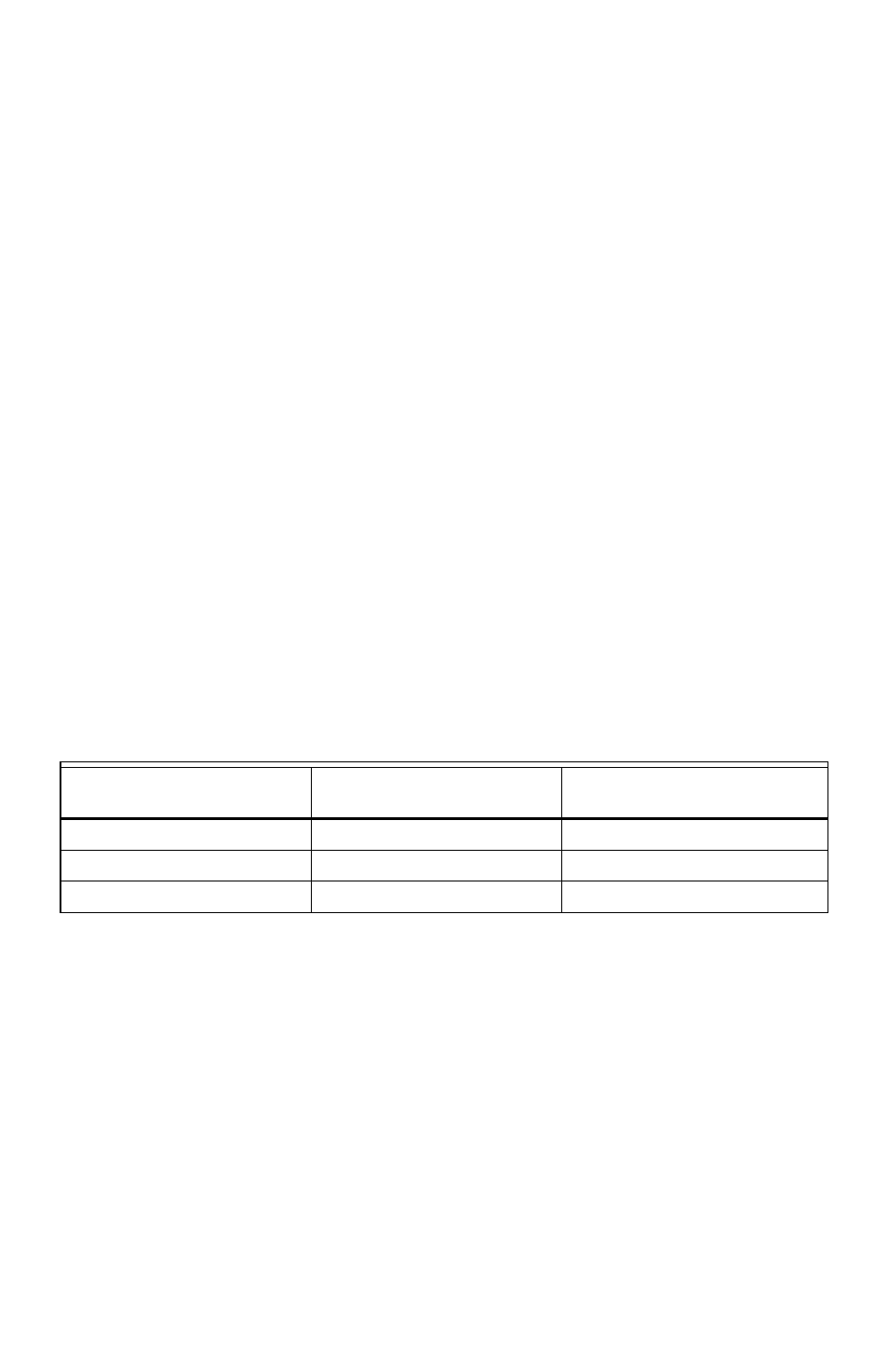
STEP 7: Using an AC Voltmeter, verify the input voltage readings are within the limits
specified below.
NOTE: Single Phase systems, the voltages are measured Phase to Neutral.
Step 8: Remove power from the unit by de-energizing the external switch.
Meter Input Voltage
Configuration
Nominal Voltage
Limits (+/- 10%)
120/208V, 2 Ph, 3 Wire
120 VAC
108 to 132 VAC
120/240V, 2 Ph, 3 Wire
120 VAC
108 to 132 VAC
277V, 1 Ph, 2 Wire
277 VAC
250 to 304 VAC