6 current sensor wiring, Class 1000 meter – E-Mon E10-2277200JKIT User Manual
Page 14
CLASS 1000 METER
62-0388-01
14
4.6 Current Sensor Wiring
Once all the current sensors are installed on their appropriate phase conductors, you
can begin terminating the current sensors on to the Class 1000 main power board.
The current sensor leads can be extended up to 2,000 feet (using #14-22 AWG wire)
for remote monitoring applications. Consult your local electrical codes for proper wire
sizing (#22 AWG twisted pair wire with a black and white conductor, rated for 600 VAC
recommended.)
The current sensor connection points are located on the bottom right of the main
power board. Three removable plugs exist, one for each current sensor phase input.
The header portions of the connectors are labeled A, B, and C. Text on the plastic
cover of each of the connectors instruct you which terminal of the plug is for the white
conductor and which terminal is wired to the black conductor. Once each current
sensor is wired to its respective plug, insert each plug into the appropriate header.
Input C is not used with the Class 1000 meter.
4.7 MAINS Line Voltage & Current Sensor Wiring
Diagrams
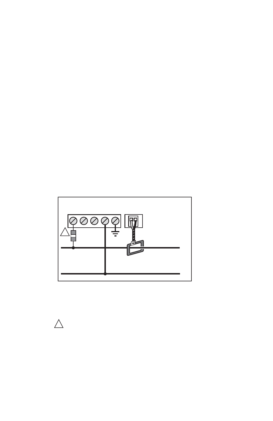
Fig. 6. Single-Phase, 2-Wire Connection 120/240 Volt Single-Phase
∅A ∅B ∅C
∅A
W B
N
LINE VOLTAGE
CURRENT SENSOR
∅A
N
SINGLE-PHASE, 2-WIRE CONNECTION
120 or 277-VOLT SINGLE-PHASE
LOAD SOURCE
M33179
NOTES:
LINE VOLTAGE CONNECTION: #14 AWG
SENSOR CONNECTION: B = BLACK W = WHITE
SHORTING LINK MUST BE INSTALLED ON B- AND C-PHASE CURRENT SENSOR TERMINALS.
1/10-AMP INLINE FUSES RECOMMENDED.
1
1
PE