Teledyne 6000B - Photometric analyzer User Manual
Page 18
2 Installation
Model 6000B
2-4: Part I
Teledyne Analytical Instruments
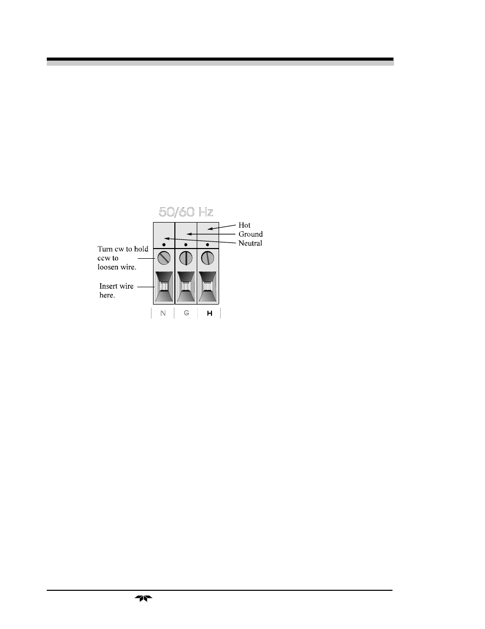
Primary Input Power:
The power supply in the Model 6000B will
accept a 115 Vac, 50/60 Hz power source. See Figure 2-4 for detailed
connections.
DANGER: Power is applied to the instrument's circuitry as
long as the instrument is connected to the power
source. The standby function switches power on or
off to the displays and outputs only.
Figure 2-4: Primary Input Power Connections
Fuse Installation:
The fuse holders accept 5 x 20 mm, 4.0 A, T
type (slow blow) fuses. Fuses are not installed at the factory. Be sure to
install the proper fuse as part of installation (See Fuse Replacement in
chapter 4, maintenance.)
Analog Outputs:
There are eight DC output signal connectors on
the ANALOG OUTPUTS terminal block. There are two connectors per
output with the polarity noted. See Figure 2-5.
The outputs are:
0–1 V dc % of Range: Voltage rises linearly with increasing sample con-
centration, from 0 V at 0% to 1 V at 100%. (Full
scale = 100% programmed range.)
0–1 V dc Range ID:
0.25 V = Low Range, 0.5 V = Medium Range,
0.75 V = High Range, 1 V = Cal Range.
115VAC
- 1220 - Multipoint flammable gas and vapor detection system (50 pages)
- 212R - Thermal conductivity analyzer (28 pages)
- 235 - Thermal conductivity analyzer (38 pages)
- 275R - Portable turbine generator purge gas analyzer (21 pages)
- 2000A-EU - General purpose thermal conductivity analyzer (86 pages)
- 2000XTC - Thermal conductivity analyzer (40 pages)
- 2010A - Split architecture thermal conductivity analyzer (110 pages)
- 2010B - Split architecture thermal conductivity analyzer (98 pages)
- 2020 - Explosion proof thermal conductivity analyzer (80 pages)
- 2120 - Trace Nitrogen in Argon Analyzer (66 pages)
- 2120XL - Trace Nitrogen Analyzer (85 pages)
- 2230R - Process Hydrogen Analyzer (26 pages)
- 2240 – Portable Handheld Hydrogen Leak Detector, 3rd generation (updated 1/31/11) (30 pages)
- 2240 - Portable Handheld Hydrogen Leak Detector, 3rd generation (revision 2/29/08) (40 pages)
- 2240 – Portable Handheld Hydrogen Leak Detector, 2nd generation (13 pages)
- 2750 - Portable turbine generator gas analzyer (40 pages)
- 300P - Percent oxygen analyzer (24 pages)
- 306WA - Analog trace oxygen analyzer (46 pages)
- 311 - Portable trace oxygen analyzer (19 pages)
- 311D - Portable trace oxygen analyzer with digital meter (18 pages)
- 311XL - Portable trace oxygen analyzer (18 pages)
- 316RA / RB / RAD / RBD - Oxygen analyzers (24 pages)
- 319R - Oxygen analyzer (23 pages)
- 320 Series - Portable oxygen detectors (24 pages)
- 326, 327 and 328 - Oxygen analyzers (45 pages)
- 329R - Oxygen analyzer (22 pages)
- 335 - Analog control room monitor for personnel safety (24 pages)
- 356WA - Analog trace oxygen analyzer (42 pages)
- 3000MA - Paramagnetic oxygen analyzer (63 pages)
- 3000MA - Paramagnetic oxygen analyzer Addendum (2 pages)
- 3000MB - Paramagnetic oxygen analyzer (59 pages)
- 3000PA - General purpose percent oxygen analyzer (69 pages)
- 3000PAEU - General purpose percent oxygen analyzer (78 pages)
- 3000PB - Bulkhead mount percent oxygen analyzer (82 pages)
- 3000TA - General purpose trace oxygen analyzer (75 pages)
- 3000TA-EU - General purpose trace oxygen analyzer (89 pages)
- 3000TA-XLEU - Trace oxygen analyzer (108 pages)
- 3000TB - Bulkhead mount trace oxygen analyzer (78 pages)
- 3000TB-XL - Trace oxygen analyzer (78 pages)
- 3000ZA - Trace oxygen analyzer (81 pages)
- 3000ZA-3X - Trace oxygen analyzer (72 pages)
- 3000ZA2G - Zirconium oxide analyzer (72 pages)
- 3000 Ultra Trace - PPB oxygen analyzer (72 pages)
- 3010MA - Paramagnetic oxygen analyzer, includes 0-100% range (88 pages)
- 3010MA – Paramagnetic oxygen analyzer, no 0-100% range – (superceded) (88 pages)