4 front panel, Figure 1-1 model 2120 front panel – Teledyne 2120 - Trace Nitrogen in Argon Analyzer User Manual
Page 13
Trace Nitrogen in Argon Analyzer
Introduction
• Low Flow Switch—cuts power to the ionizer if the sample flow
falls below a setpoint.
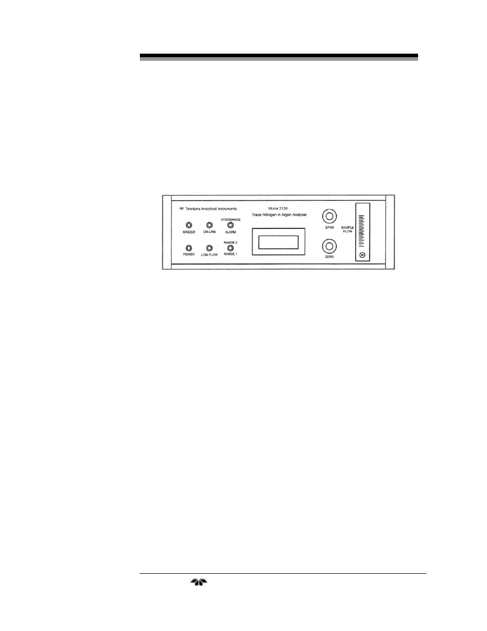
1.4 Front Panel
Operator controls and displays are located on the front panel as
shown in Figure 1-1.
Figure 1-1 Model 2120 Front Panel
• Status Indicator Lights:
•
Ionizer Light —Illuminates when the 255 Hz power
supply is operational and its output is being supplied to
the switching relay.
•
Power Light— Illuminates when main power switch is
on and the fuse is good. Switch and fuse are both
located in the power entry module on the back of the
analyzer.
•
On-Line Light—Illuminates when ionizing voltage is
applied to the analytical cell. The analyzer requires a
sample flow of at least 0.2 cfh (100 ccpm) for the
analytical cell to come on line.
•
Low Flow Light— Illuminates when flow to the
analyzer is less than 0.2 cfh (100 ccpm). When this
occurs the ON-LINE light will be off indicating that no
ionizing voltage is being applied to the analytical cell.
•
Overrange Alarm Light— Illuminates when discharge
brightness deteriorates due to an unusually high level
of impurity in the sample gas.
Teledyne
Analytical
Instruments
3