SPP Pumps Unistream User Manual
Page 6
Manual No/Rev
W21-002E / 10
Operators Instructions for
Unistream Centrifugal Pumps
Our policy is one of continuous improvement and we reserve the right to alter specifications at any time
Page 6 of 24
4.3 Pump Preparation
Abrasion
and
Entrapment
Hazard
Do NOT touch any moving or
rotating parts. Guards are provided to
prevent access to these parts, where they
have been removed for maintenance they
MUST be replaced before operating the
equipment.
Remove packaging but leave the flange
covers in place, check that impeller rotates
freely by hand by turning the shaft.
4.4 Pump Installation
It is recommended that the pump unit is
fitted to the baseplate before fitting the motor
and coupling. The distance between shaft
ends should be established to suit the
coupling by reference to the manufacturer's
instructions.
4.5 Shaft Alignment
To minimise the side load on the bearings
and to achieve full coupling and bearing life.
It is recommended that the shafts are
aligned as accurately as possible i.e. well
below the allowable misalignment of the
coupling.
Refer to the coupling manufacturer's
instructions or proceed generally thus:
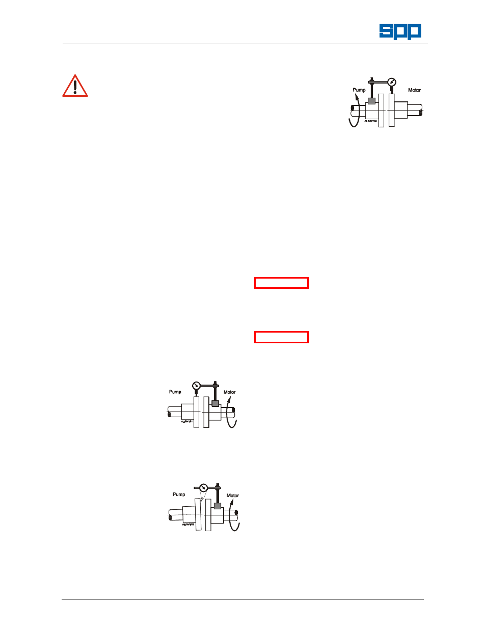
a) Lateral Alignment
Mount a dial gauge
on the motor shaft
or coupling with the
gauge running on
the
machined
diameter
of
the
pump coupling. Turn the motor shaft and
note the total indicator reading.
b) Angular Alignment
Mount a dial gauge
on the motor shaft
or coupling to run
on a face of the
pump coupling as
near the outside
diameter
as
possible. Turn the motor shaft and note
the total indicator reading.
c) Confirm Lateral Alignment
Mount
the
dial
gauge on the pump
shaft or coupling
with
the
gauge
running
on
the
machined diameter
of
the
motor
coupling. Turn the pump shaft and note the
total indicator reading.
d) Adjustment
The motor must be shimmed and re-
positioned to align the shafts within the
coupling manufacturer's specifications.
e) Alternative Method
If a dial gauge is not available, callipers or
taper gauge may be used to measure the
distance between the coupling flanges at
four points around the circumference and a
straight edge used to check the lateral
alignment of the outer flange diameters.
Shaft alignment must be
checked again after the
final positioning of the pump unit and
connection to pipework as this may have
disturbed the pump or motor mounting
positions.
If hot liquids (above
80°C)
are
being
pumped, alignment should be checked and
reset with the pump and motor at their
normal operating temperature. If this is not
possible, SPP Pumps Ltd. can supply
estimated initial offset figures to suit
extreme operating temperatures.
4.6 Suction Pipework
The run of suction pipework must be such
that air can NOT become trapped where it
would be sucked into the pump on starting.
The bore of suction pipe is recommended
to be one or two sizes larger than the pump
suction branch and reducers if used must
be eccentric to eliminate the possibility of
an air pocket being formed.
Bends in the suction pipeline should be as
large as possible, the pipe made as short
and as straight as possible and all joints
must be fully airtight. If fitting a foot valve, it
should have a free area of one and a half
times the area of the suction pipe.
ATTENTION
ATTENTION