SPP Pumps Unistream User Manual
Page 13
Operators Instructions for
Unistream Centrifugal Pumps
Manual No/Rev
W21-002E / 10
Our policy is one of continuous improvement and we reserve the right to alter specifications at any time
Page 13 of 24
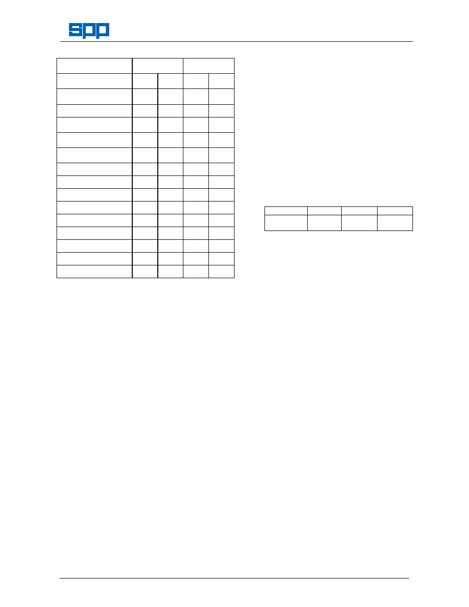
Dia. 1 = Outside Dia.
of Impeller
Suction Side
Drive Side
Dia. 2 = Inside Dia.
of Impeller
Dia. 1
Dia. 2
Dia. 1
Dia. 2
Pump Size:
Tolerances
-0.1
F8
-0.1
F8
32/13 32/16
69.7
70
-
-
32/20 32/26 40/13
40/16 40/20
79.7
80
-
-
40/26 50/13 50/16
50/20
94.7
95
-
-
50/26 65/13 65/16
65/20 65/26
114.7
115
-
-
65/32
129.6
130
124.6
125
80/16 80/20 80/26
129.6
130
-
-
80/32
139.6
140
134.6
135
100/20 100/26
159.6
160
-
-
100/32
159.6
160
154.6
155
100/40
159.6
160
159.6
160
125/26
179.6
180
-
-
125/32 125/40
179.6
180
179.6
180
150/32 150/40
199.6
200
199.6
200
6.6 Re-assembly of the Pump.
The pump unit may be re-assembled in the
reverse manner to disassembling. To ensure
correct and trouble free operation, care
should be taken on re-assembly and the
following precautions taken:
Cleanliness is important ensure that all
pump components together with the working
areas, are completely free of foreign matter,
dirt and dust.
All gasket faces are to be properly cleaned
and new gaskets fitted. Gasket and other
spares kits are available from SPP Pumps
Ltd. Spares department, for details refer to
Section 8 - Parts Lists.
It is recommended that only spare parts
manufactured by and obtained from SPP
Pumps Ltd., are used during maintenance
re-assembly of any Unistream range pump.
The company cannot be held responsible for
any failure, which may cause danger to
property or health, arising from the use of
spare parts manufactured and supplied by
others, these will also invalidate the pump
warranty.
When ordering spare parts it is essential to
quote the pump serial number from the
identification plate and the required part
number(s) as shown in the parts list in
Section 8.
If new proprietary parts such as bearings
and lip seals are to be fitted, ensure they are
the correct size, grade and quality.
When fitting new bearings they should be
pre-heated in an oil bath to 80
0
C for a short
period of time. This will enable the bearing to
be easily slid on the shaft seating and when
cool will give a positive shrink fit. Always
ensure bearings abut correctly against shaft
shoulder.
After the shaft (21.1), pair of gaskets (42.02)
and the bearing covers (36.0) have been
fitted to the bearing housing (33.0), the end
float of the rotor should be within the
following dimensions
Rotor End Float.
Shaft Unit
25
35
45
Rotor End
Float
0.1 to
0.75 mm
0.3 to
0.94 mm
0.3 to
0.94 mm
Check the locking washer(93.0) for wear or
damage, replace if necessary.
6.7 Installation of Mechanical Seals
Lubricate the outer surface of the stationery
element of the mechanical seal (43.3) with
soapy water or silicone grease (not oil),
ensure that it is square to its housing in the
casing cover (16.1) and push home by hand,
taking care not to apply excessive force or to
damage the sealing surface. Check that it
has been seated fully and that the sealing
surface is clean and undamaged.
Refit the casing cover to the bearing
housing, fit the bolts for the bolted casing
cover, tightening them uniformly and in
diagonally opposed pairs sequence.
Position the rotating seal face over the shaft
to butt against the static seal element, taking
care not to damage the sealing surfaces.
Insert the gasket (40.01) into the sleeve and
ensure that it is properly seated.
Lubricate the inner and outer surfaces of the
sleeve lightly with silicone grease, fit the
spring assembly in position and mount the
sleeve over the shaft, compress the spring
and insert the impeller key to retain the
sleeve in position. Ensure that the rotating
seal face is floating against the spring before
re-fitting the impeller.
For SPP Pumps Ltd. Spares and Service
Department, telephone 0118 9323123, see
the back cover for further details of SPP
Pumps Ltd. After Sales Service.