General description, Assembly and installation, Trapped air unsupported pipe – SPP Pumps Instream User Manual
Page 5
Operators Instructions for
Instream Centrifugal Pumps
Manual No/Rev
W23-001E / 8
Our policy is one of continuous improvement and we reserve the right to alter specifications at any time
Page 5 of 16
3. General Description
The SPP Pumps Ltd range of Instream Pumps
are centrifugal pumps that comply with Pump
Standard DIN24255.
The mechanical assembly comprises an
electric motor fitted with an extended shaft to
carry a double shrouded type impeller. This is
connected by a support frame to an in line
volute casing fitted with wear ring(s). The
motor, frame, shaft and impeller assembly can
be withdrawn from the volute for maintenance
without disconnection of pipe work.
The in line suction and discharge branches
are the same size. The pump must be
mounted with the motor shaft vertical and
above the pump. A mounting position is
provided on the volute casing for attachment
to suitable foundations.
The shaft is sealed with a standard
mechanical seal.
Nameplate details are shown on the back
cover, full pump specification can be supplied
on a data sheet, if requested.
Note
(1) - Head specified is the Duty Head generated by the
pump only.
(2) -Suction pressure must be included when assessing the
Maximum Working Pressure.
For details of the motor supplied, refer to the
manufacturer's instructions in Appendix I.
4. Assembly and Installation
Shearing Hazard
Do NOT place fingers or hands etc.
into the suction or discharge pipe
outlets and do NOT touch the
impeller, if rotated this may cause severe
injury. To prevent ingress of any objects,
retain the protection covers or packaging in
place
until
removal
is
necessary
for
installation.
4.1
Initial Inspection for Damage
During transport and storage, accidental
damage to the pump may have occurred.
When the pump is to be installed, or in the
event of a handling accident, carefully check
that no damage has been sustained by the
pump before installation and commissioning.
4.2
Preparation for Mounting
Before installation, check that the pump
mounting location is suitable for accepting the
pump. Refer to Section 8, for details of pump
installation dimensions or to a certified
General
Arrangement
Drawing
when
available.
4.3
Pump Preparation
Abrasion & Entrapment Hazard
Do NOT touch any moving or rotating
parts. Guards are provided to prevent
access to these parts, where they have been
removed for maintenance they MUST be
replaced before operating the equipment.
Remove packaging but leave the flange
covers in place, check that impeller rotates
freely by hand by turning the shaft.
4.4
Pump Installation
Instream pumps are to be mounted on
substantial
rigid foundations to reduce
vibrations. A bolt hole is provided within a
circular foot for fixing to a baseplate or
framework.
4.5
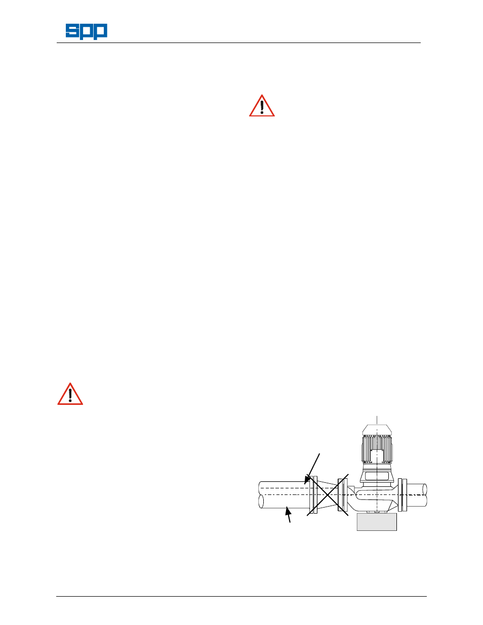
Suction Pipework
The run of suction pipework must be such that
air can NOT become trapped where it would
be sucked into the pump on starting. The bore
of suction pipe is recommended to be one or
two sizes larger than the pump suction branch
and reducers if used must be eccentric to
eliminate the possibility of an air pocket being
formed.
Bends in the suction pipeline should be as
large as possible, the pipe made as short and
as straight as possible and all joints must be
fully air tight. If fitting a foot valve, it should
have a free area of one and a half times the
area of the suction pipe.
Unacceptable Suction Pipework
Trapped Air
Unsupported Pipe
INSTSUC1.WMF
Where pumping water at temperatures above
70°C, care must be taken to ensure that
enough pressure is available at the impeller
entry to prevent vaporisation.
An appropriate fine strainer is recommended