Pump fault finding – SPP Pumps Auto Prime Q Series - QI200 User Manual
Page 13
Operators Instructions for
AUTOPRIME Q Range Pump Unit
Manual No/Rev
W72-008E / 9
Our policy is one of continuous improvement and we reserve the right to alter specifications at any time
Page 13 of
18
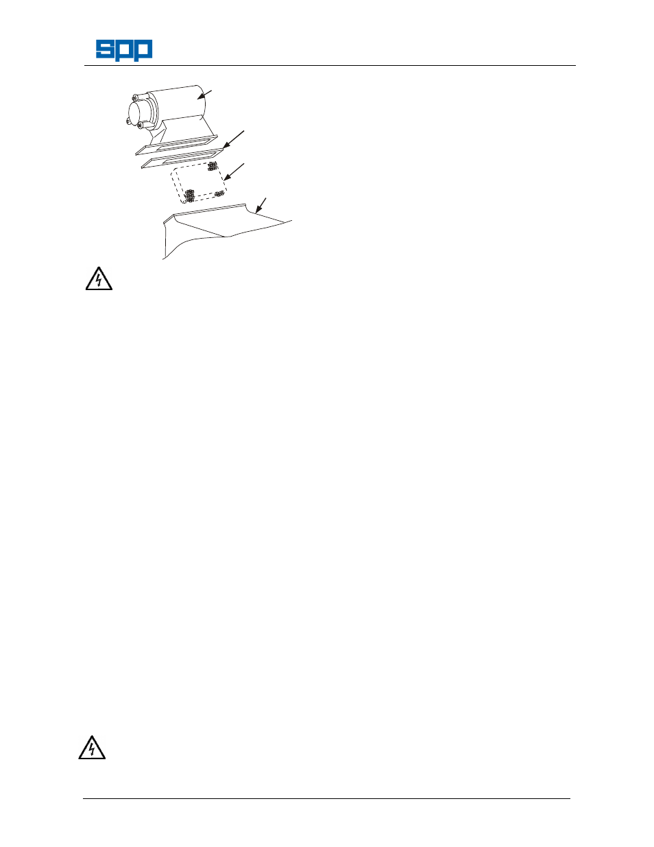
AIRFILTER2
AIR FILTER &
SOLENOID VALVE
(Valve not shown)
GASKET
KNITMESH
PRIMING
TANK
Remove the terminal box cover from the
solenoid valve and disconnect the wiring
inside. Note the positions of the terminations
for reconnection.
Separate the filter housing from the priming
tank by removing eight nuts and the rubber
gasket. The knitmesh can now be removed
from the priming tank.
Clean the knitmesh filter in water and dry it.
Inspect the filter and the rubber gasket and
replace any damaged items.
7.13 Level Sensing Probes & Priming Control
Box
The level sensing probes should be
withdrawn and cleaned periodically to keep
them in workable condition. Wipe any
deposit from the stainless steel tips.
The control box and cables to the level
sensing probes are sealed units for which no
customer maintenance is required. If these
items fail they may be replaced and/or
returned to SPP Pumps for examination.
7.14 Pump Impeller and Front Wear Plate
The impeller can be inspected for wear and
corrosion after the suction quick release
connection has been removed. Check the
inlet duct for signs of damage or blockage.
The impeller to wear plate clearance should
be 0.3 - 0.5mm.
A more thorough examination can be
conducted after the inlet duct and front wear
plate have been removed. The front wear
plate is clamped between the inlet duct and
the volute of the pump.
Disconnect the battery negative lead to
prevent accidental starting of the pump.
Remove the priming tank. Remove the front
section of the tank shroud. Remove the nuts
retaining the inlet duct and remove the duct.
Remove the front wear plate by screwing two
M16 bolts into the jacking holes on the wear
plate.
Inspect the impeller and wear plate for
damage and corrosion.
Before re-assembly ensure all ‘O’ rings are
in good condition, clean and well greased.
Impeller to front wear plate clearance can be
altered by shimming. Measure the clearance
with a feeler gauge inserted through the
suction. When measuring the clearance
temporarily fit the nuts and clamp the front
wear plate to the volute to ensure that the
wear plate is fully home.
Refit the inlet duct, priming tank, front
shroud, front panel and Quick release
connection.
8. PUMP FAULT FINDING
Refer to the operator’s problem solving
routines in section 5.5 and ensure that these
faults are not present.
These checks to be done by trained service
engineers:
8.1
Checking the operation of the priming
system
Disconnect the suction hose. Place a flat
board over the suction fitting to check that
the priming system and vacuum pump is
working.
If a vacuum gauge is fitted to the suction the
vacuum pump should produce a vacuum of
9 metres water.
8.2
Check the vacuum pump drive belts
The vacuum pump drive belts run between
the pump shaft and the electric clutch on the
vacuum pump. See the maintenance
instructions in section 7.5 for the belt
tensioning method.
8.3
Check the vacuum pump clutch
The vacuum pump clutch is electrically
operated. If the clutch is disengaged the
belts still turn but the centre of the clutch will
be stationary.
The clutch requires 12 volts to actuate it.
This voltage controlled by a timer and
supplied via a relay by wire No 22 of the
wiring loom. If the wiring is disturbed during
investigations ensure that it is replaced
correctly.