Maintenance & service instructions – SPP Pumps Auto Prime Q Series - QI200 User Manual
Page 10
Manual No/Rev
W72-008E / 9
Operators Instructions for
AUTOPRIME Q Range Pump Unit
Our policy is one of continuous improvement and we reserve the right to alter specifications at any time
Page 10 of 18
7. MAINTENANCE & SERVICE INSTRUCTIONS
.
These instructions are for trained pump
service engineers.
Where instructions in this section are
followed by (LH) or (RH) this indicates either
the left hand or right hand side of the unit
looking from the pump (towbar) end
7.1 Preparation for Maintenance
Electric Shock & Accidental Starting
Hazard ISOLATE the equipment from any
mains
supply
connected
before
any
maintenance work is done.
For diesel engine driven pumps disconnect
the negative battery lead to prevent
inadvertent starting.
To avoid the possibility of maintenance
personnel inhaling dangerous fumes or
vapours.
It
is
recommended
that
maintenance work be carried out away from
the pump location by removal of the pump
unit to a suitable maintenance area.
No special tools are required for dismantling
and re-assembling, however, it is important
to ensure the suitable lifting equipment is
available and that the work is carried out in a
clean area.
7.2 Pump Bearings
The pump shaft runs on three bearings: a
roller bearing on the impeller end of the shaft
and a pair of angular contact bearings on the
drive end of the shaft. These bearings are
grease lubricated.
BRGHSGA
DRIVE END
GREASE
NIPPLE
PUMP END
GREASE
NIPPLE
Grease is applied through two grease
nipples, one for the roller bearing and one for
the pair of angular contact bearings located
on the left side of the bearing bracket. Do
not over grease. Ten strokes (15 grams) of a
hand held grease gun at the specified
intervals are sufficient.
7.3 Mechanical Seals
The mechanical seals are cooled and
lubricated by oil. The oil reservoir is mounted
on top of the non-return valve cover. The
system oil capacity is approximately two
litres. The bottle should be filled to the MAX
mark when the unit is cold.
Only use oil of the correct grade
(see Technical Data section).
7.4 Fuel Filler Gauge
Located in neck of fuel filler. Inspect for
debris. Remove and clean if necessary.
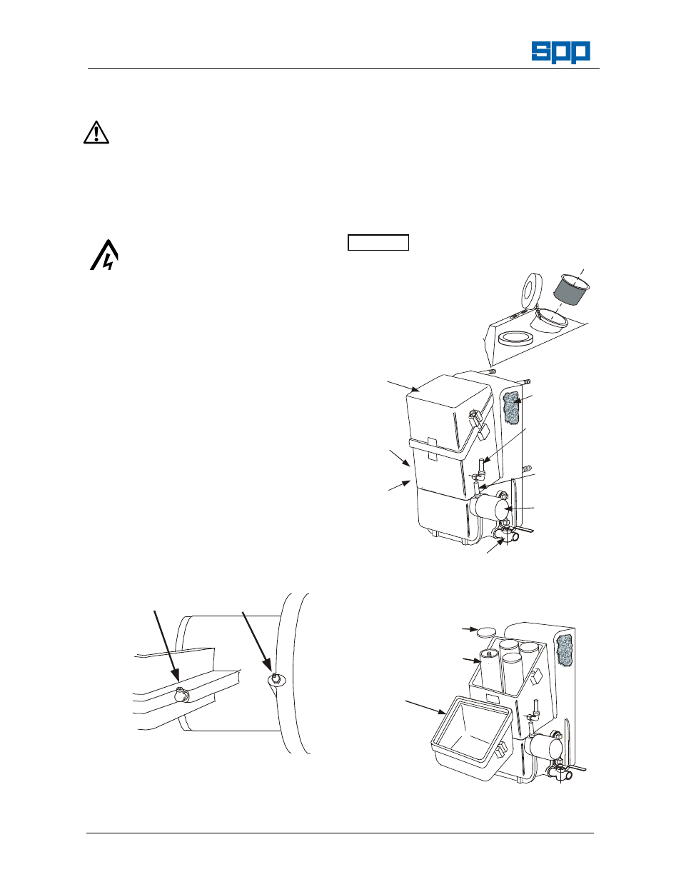
7.5 Coalescer Maintenance
Daily, check the oil level in the coalescer
sump. If the level has risen, check for water
contamination, drain off any water present
and top-up the oil to the level between the
marks on the dipstick. Water is removed by
means of the drain tap fitted to the side of
the coalescer sump.
7.6 Coalescer Filter Element Replacement
Coalescer filter elements must be replaced
after the first 500 hours or one month of
operation of a new vacuum pump, after
which they need to be replaced only when
the
inside
surface
becomes
heavily
discoloured i.e. black or dark brown. These
elements cannot be cleaned, new elements
must be fitted when required thus:
NEWC
OAS3
REMOVE THE COALESCER LID
UNSCREW THE
ELEMENT CAPS
LIFT ELEMENTS
AND REPLACE
REPLACE THE
COALESCER
LID
Ensure that the seals at the top and bottom
of each filter element are fitted correctly.
ATTENTION
FU
EL
FI
LT
ER
NEWC
OAS1
OIL FILLER
& DIP STICK
EXHAUST
PORT
(FAR SIDE)
COALESCER
LID
WATER DRAIN TAP
FILTER
MESH
OIL
SCAVENGE
PIPE
OIL
FEED
PIPE
OIL
FILTER