SPP Pumps Auto Prime Q Series - QI200 User Manual
Page 11
Operators Instructions for
AUTOPRIME Q Range Pump Unit
Manual No/Rev
W72-008E / 9
Our policy is one of continuous improvement and we reserve the right to alter specifications at any time
Page 11 of
18
Do not over tighten the retaining
knob as this will distort and crush
the filter element.
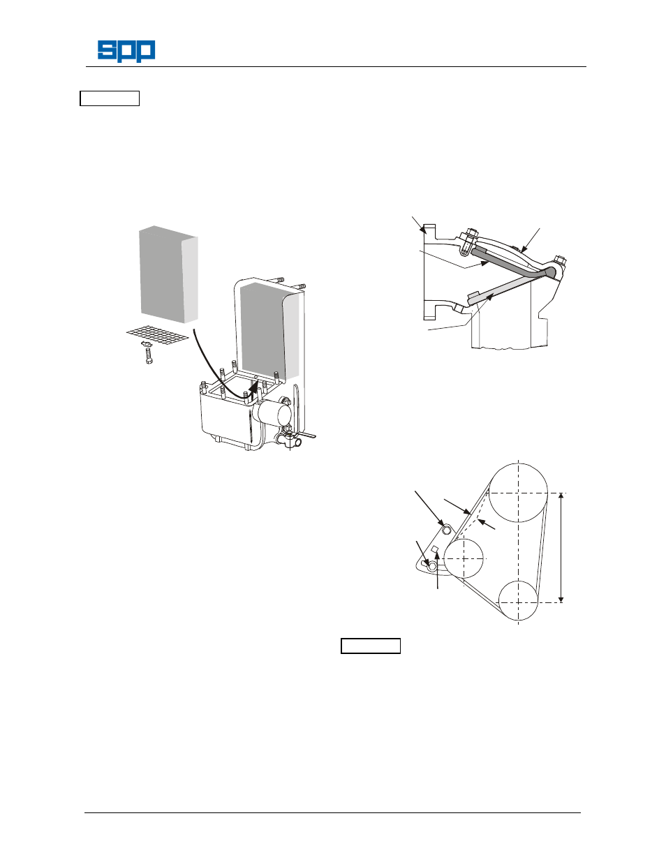
7.7 Coalescer Filter Mesh
Every year or more frequently if the pump
has been operating in a dusty atmosphere or
when the coalescer oil has become dirty, it is
recommended that the priming tank filter
mesh is replaced.
NEWC
OAS2
COMPRESS THE
FILTER & PUSH
UPWARDS INTO
PLACE. RETAIN
WITH MESH AS
SHOWN
Drain the coalescer oil, disconnect the oil
feed pipes and remove the coalescer lid and
the coalescer element housing complete
with the filter elements. Remove the mesh
retaining the filter to give access for removal
of the knitmesh filter.
It is recommended that a new gasket is fitted
before re-fitting the coalescer element
housing.
The oil feed pipes should be cleaned in a
similar manner and blown through with an air
line.
7.8 Non-Return Valve
The non-return valve should be checked
regularly for freedom of movement, absence
of debris and good seating. The valve seat
should also be checked for damage or wear.
The flap type non-return valve is built in to
the pump casing and located under a cast
cover on top of the pump behind the
discharge flange. It consists of a hinged
rubber disc resting on a seat machined onto
the volute. The disc and seat can be
examined through the discharge flange once
the quick release hose connection is
removed. Check that the disc sits cleanly
onto the seat and that nothing is trapped
between the hinge and the casting (both
above and below). Check that the disc is not
worn or torn and that the seat is not
excessively
pitted.
A
more
detailed
examination can be undertaken by removing
the cover on top of the valve. Replace the
cover gasket when refitting the valve cover.
NRV
1
FLAP
DISCHARGE
FLANGE
FLAP TYPE
NON RETURN
VALVE
ACCESS
COVER
FLAP
OPEN
FLAP
CLOSED
7.9 Vacuum Pump Belt Tension
To adjust belt tension, loosen the pivot and
locking bolts and using a spanner on the
adjustment aid, slide the pulley outward.
When the correct belt tension is obtained re-
tighten the locking bolt and the pivot bolt.
5kgs
6mm
1
9
0
m
m
PIVOT
BOLT
LOCKING
BOLT
1/2" SQ
ADJUSTMENT
AID
BELTENS1
Do not under-tension belts under
any circumstances.
7.10 Vacuum Pump Belt Replacement
Remove the vacuum pump drive guard if
fitted.
Slacken and remove the belt tension device
by removal of the pivot bolt and the locking
bolt.
From the main pump drive coupling, remove
the three screwed pins from the rubber
coupling to give a gap between the engine
ATTENTION
ATTENTION