SPP Pumps Auto Prime - High Flow Range XF300 & 400 User Manual
Page 7
Operators Instructions for
XF300 & XF400 Range Centrifugal Pumps
Manual No/Rev
W77-009E / 2
Our policy is one of continuous improvement and we reserve the right to alter specifications at any time
Page 7 of 23
4.4 Pump Installation
It is recommended that the pump unit is
fitted to the baseplate before fitting the
motor and coupling. The distance between
shaft ends should be established to suit the
coupling by reference to the manufacturer's
instructions.
4.5 Shaft Alignment
To minimise the side load on the bearings
and to achieve full coupling and bearing life,
it is recommended that the shafts are
aligned as accurately as possible i.e. well
below the allowable misalignment of the
coupling.
Refer
to
the
coupling
manufacturer's instructions or proceed
generally thus:
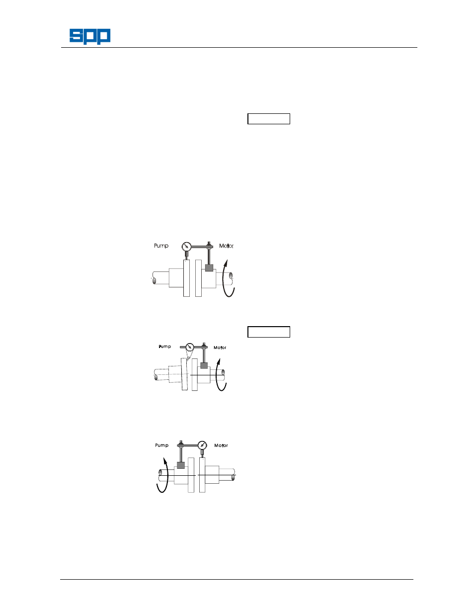
a)
Lateral Alignment
Mount a dial gauge
on the motor shaft
or coupling with the
gauge running on
the outer machined
diameter
of the
pump coupling. Turn the motor shaft and
note the total indicator reading.
b)
Angular Alignment
Mount a dial gauge
on the motor shaft
or coupling to run
on a face of the
pump coupling as
near the outside
diameter
as
possible. Turn the
motor shaft and note the total indicator
reading.
c)
Confirm Lateral Alignment
Mount
the
dial
gauge on the pump
shaft or coupling
with
the
gauge
running
on
the
outer,
machined
diameter
of
the
motor
coupling.
Turn the pump shaft and note the total
indicator reading.
d)
Adjustment
The motor must be shimmed and re-
positioned to align the shafts within the
coupling manufacturer's specifications.
e)
Alternative Method
If a dial gauge is not available, callipers or
taper gauge may be used to measure the
distance between the coupling flanges at
four points around the circumference and a
straight edge used to check the lateral
alignment of the outer flange diameters.
Shaft alignment must be checked again
after the final positioning of the pump unit
and connection to pipework as this may
have disturbed the pump or motor mounting
positions.
4.6 Suction Pipework
It is recommended that the pump is
installed as near to the liquid source as
possible
Any rigid pipework should be supported
independently and close to the pump so
that no strain is transmitted to the pump
when the flange bolts are tightened. Use
pipe supports at intervals necessary to
provide support. When expansion joints are
used in the piping system, they must be
installed beyond the piping supports closest
to the pump.
Collapsible hoses must not be used on
the suction side of the pump.
Install piping as straight as possible,
avoiding unnecessary bends. Where
necessary use long sweep 90
°
bends or
fittings to decrease friction losses.
Make sure that all suction piping joints are
air tight. Provide pipe expansions when hot
fluids are to be pumped. Where reducers
are used, eccentric reducers (tapered side
down) are to be fitted in horizontal suction
lines and straight taper reducers in vertical
discharge lines. Undulations in the pipe
runs or misuse of reducers may cause the
formation of air pockets in the pipe and thus
prevent the efficient operation of the pump.
The suction (and discharge) pipes can be
one or two sizes larger than the pump
flange connections. A horizontal suction line
should have a gradual rise to the pump.
A correctly sized filter or strainer must be
fitted to hold back larger items.
The suction pipe work should be flushed
ATTENTION
ATTENTION