Installation, Warning – Fulton Vertical Coil (FT-C_S) Thermal Fluid (hot oil) Heater User Manual
Page 30
© The Fulton Companies 2013
2-24
INSTALLATION
FTCS-IOM-2013-1114
SECTION 2
!
WARNING
All information in this manual is for
reference and guidance purposes,
and does not substitute for required
professional training, conduct,
and strict adherence to applicable
jurisdictional/professional codes and
regulations.
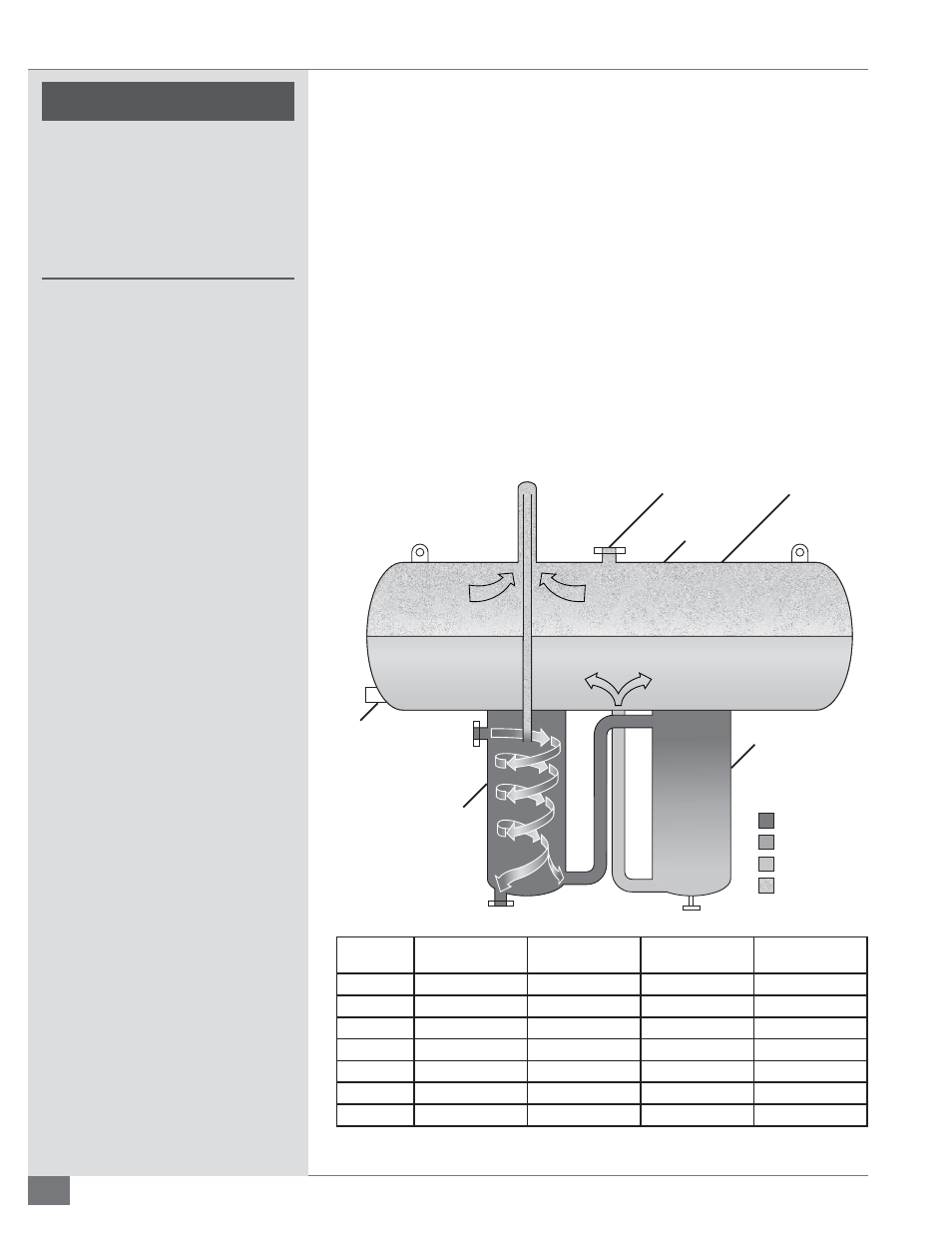
Combination Deaerator/Thermal Buff er/Expansion Tank
Fulton Thermal’s effi
cient design combines the operation of the expansion,
deaerator, and thermal buff er tanks. Installation is considerably simplifi ed by
virtue of this arrangement.
The expansion section is vital to the thermal fl uid system. From ambient to
operating temperature, the thermal fl uid in the system will typically expand
in the range of 25% to 50%, and a vessel capable of handling this expansion is
mandatory. The customer should confi rm the expansion rate of the chosen fl uid
and system volume.
At start up, the primary purpose of the deaerator section is to remove all volatiles
from the system to avoid pump cavitation. The deaerator section also allows air
to be vented from the system on a continuous basis during operation to avoid
oxidation of the thermal fl uid, and removes other volatile particles generated by
the fl uid itself during system operation. This section of the tank must be insulated.
Vent for Piping
to Safe Catchment
Expansion
Tank
Liquid
Level
Switch
Fluid Out
Fluid In
Deaerator
Section
Thermal
Buffer
Section
Hot Fluid
Medium Fluid
Cool Fluid
Gases (Steam)
Expansion
Volume
Drain
FIGURE 13 - EXPANSION TANK DETAILS
Model
Capacity (gallons)
Initial Fill (gallons)
Available for
Expansion (gallons)
Max System Volume
FT-200-L
52
25
46
184
FT-500-L
132
40
121
525
FT-1000-L
264
80
232
1000
FT-1500-L
397
90
380
1400
FT-2000-L
528
145
444
1700
FT-3000-L
793
215
717
2600
FT-5000-L
1310
300
1168
4600