Installation, Utilities, The gas supply – Fulton Vertical Coil (FT-C_S) Thermal Fluid (hot oil) Heater User Manual
Page 13
Questions? Call (315) 298-5121, or visit us online at www.fulton.com
SECTION 2
FTCS-IOM-2013-1114
INSTALLATION
2-7
combustion or nuisance failures.
TABLE 5- MINIMUM MAKE-UP AIR REQUIREMENTS AND
RECOMMENDED AREA OF OPENING FOR VENTS
Model
Minimum
Make-Up
Air (SCFM)*
Opening Area
(in2)**Lower
Vent
Opening
Area (in2)
Upper Vent
FT-0080C
200
400
135
FT-0120C
300
600
205
FT-0160C
400
800
270
FT-0240C
600
1200
400
FT-0320C
800
1600
535
FT-0400C
1000
2000
670
FT-0600C
1500
3000
1000
FT-0800C
2000
4000
1335
FT-1000C
2500
5000
1670
FT-1200C
3000
6000
2000
FT-1400C
3500
7000
2335
FT-0400S
1000
2000
670
FT-0600S
1500
3000
1000
FT-0800S
2500
4000
1335
*Minimum make-up air requirements are based on 25% excess air at high fi re.
**Opening areas are calculated based input of a single heater and do not account
for the ventilation needs of the equipment room. These measurements are
subject to state and local regulations.
NOTE:
A properly designed make-up air system in the
equipment room will preclude these possibilities and is
required to maintain proper combustion.
7. Eliminate potential for high risk situations for particulate
matter to be in the combustion air supply (e.g., as a
result of construction and maintenance activities).
Utilities
The Gas Supply
Adhere to the following for gas supply installation:
1. Install gas piping in accordance with all applicable
codes.
2. Ensure pipe and fi ttings used are new and free of dirt or
other deposits.
3. Ensure piping is of the proper size for adequate gas
supply to the gas head assembly. Consult your gas
company for specifi c recommendations.
4. When making gas piping joints, use a sealing
compound resistant to the action of liquefi ed
petroleum gases. Do not use Tefl on tape on gas line
heads.
5. Ensure no piping stresses are transmitted to the
equipment. The equipment shall not be used as a pipe
anchor.
6. Ensure all vent connections on diaphragms, gas valves,
pressure regulators, and pressure switches (gas-fi red
units) are vented per local code.
7. On
gas-fi red units with NFPA valve trains, ensure the
vent valve is piped to atmosphere per local code. See
Figure 4.
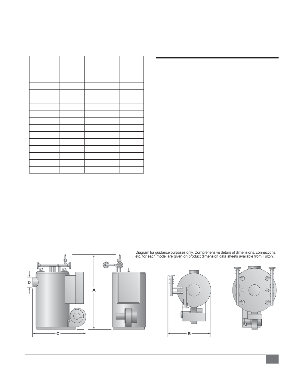
FIGURE 2 - DIMENSIONS (REFER TO TABLE 2)