Installation – Fulton Vertical Coil (FT-C_S) Thermal Fluid (hot oil) Heater User Manual
Page 12
© The Fulton Companies 2013
2-6
INSTALLATION
FTCS-IOM-2013-1114
SECTION 2
!
WARNING
All information in this manual is for
reference and guidance purposes,
and does not substitute for required
professional training, conduct,
and strict adherence to applicable
jurisdictional/professional codes and
regulations.
A qualifi ed installer, service agency
or the gas supplier must perform
installation and service on the fuel
delivery system.
Do not use matches, candles, fl ame or
other sources of ignition to check for
gas leaks.
WHAT TO DO IF YOU SMELL GAS:
Do not try to light the appliance.
Do not touch any electrical switch.
Do not use any phone in the building.
Leave building and contact gas
supplier from neighbor’s phone. If you
cannot reach gas supplier, phone the
fi re department.
When making gas piping joints,
maintain proper ventilation to reduce
breathing hazards.
An exhaust fan may draw products of
combustion into the work environment
creating a possible hazard to personnel.
4
CAUTION
It is essential that only fresh air be
allowed to enter the combustion air
system. Foreign substances, such
as combustible volatiles and lint in
the combustion system can create
hazardous conditions. If foreign
substances can enter the air stream, the
combustion air inlet must be piped to
an outside location. Failure to do so will
void the warranty.
To avoid failures due to poor
combustion, ensure make-up air system
is properly designed.
3. Ensure the equipment room air supply openings are kept clear at all times.
4. See Table 5 for minimum make-up air required and the recommended area
of each opening for each model.
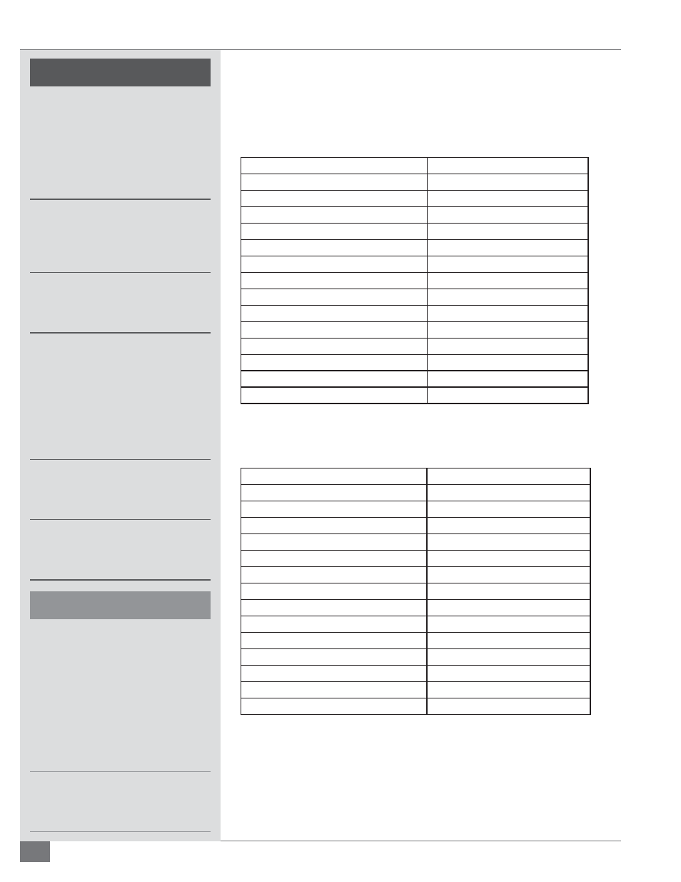
TABLE 3- APPROXIMATE FLOOR LOADING
Model
Heater Only*
FT-0080C
500
FT-0120C
400
FT-0160C
450
FT-0240C
450
FT-0320C
450
FT-0400C
450
FT-0600C
550
FT-0800C
500
FT-1000C
500
FT-1200C
400
FT-1400C
450
FT-0400S
675
FT-0600S
675
FT-0800S
525
*All weights are lbs/ft
2
TABLE 4 - RECOMMENDED MINIMUM CLEARANCES FOR PERSONNEL ACCESS/BURNER
REMOVAL
Model
Inches (Meters)
FT-0080C
109 (2.8)
FT-0120C
115 (3.0)
FT-0160C
119 (3.1)
FT-0240C
125 (3.2)
FT-0320C
133 (3.4)
FT-0400C
145 (3.7)
FT-0600C
171 (4.4)
FT-0800C
172 (4.4)
FT-1000C
173 (4.4)
FT-1200C
172 (4.4)
FT-1400C
188 (4.8)
FT-0400S
162 (4.2)
FT-0600S
170 (4.4)
FT-0800S
171 (4.4)
5. If positive forced ventilation is adopted, ensure that there will be no
appreciable pressure variation in the equipment room.
6. Avoid ventilation which creates a negative pressure in the building as it
will seriously aff ect combustion and proper operation of the stack. Please
note that exhaust fans or similar equipment can create a down draft in the
chimney or starve the burner’s air supply. Either case may result in poor