Rs-232 connection (modem use), Table 3, Table 4 – ADTRAN TRACER 4206 Plan A User Manual
Page 29: Tracer 4106/4206 (dce) to personal computer (db-9)
TRACER 4106/4206 System Manual
Section 3 Engineering Guidelines
612804206L2-1A
© 2004 ADTRAN, Inc.
29
RS-232 Connection (Modem Use)
Modem controls, discussed in Section 5, User Interface Guide, enable or disable modem control
through the RS-232 interface. When this option is enabled from a standard terminal connection, all
RS-232 communications cease until a modem with a null modem adapter is attached between the
TRACER 4106/4206 and the data modem. Configure the data modem for
AUTO ANSWER
and
9600
BPS
.
When the user connects via the modem to the TRACER 4106/4206 unit, communications via the RS-232
port resume. If a user accidentally enables modem control from a terminal and disrupts the RS-232
communication, pressing <Ctrl + Z> three times will temporarily disable the modem control option (until
the system is reset) and will access the system option to disable modem control.
The TRACER 4106/4206 must be interfaced to a modem via an RS-232 null modem adapter or cable. The
null modem converts Clear To Send (CTS) and Data Set Ready (DSR) into Ready To Send (RTS) and Data
Terminal Ready (DTR), respectively. These signals indicate (to most modems) that a valid DTE terminal
device is present. The null modem interface must route Carrier Detect (CD) on pin 8 directly from the
modem. When using the RS-232 interface for modem control, the modem must source CD only when
actually connected to a carrier.
When
M
ODEM
C
ONNECTION
is selected in the menu system, the TRACER 4106/4206 will de-assert DTR
and DSR for a time greater than 20 msec. The null modem consequently drops DTR and RTS at the
modem interface, signaling the modem to hang up the line. If password functionality is enabled in the
TRACER 4106/4206, selecting
M
ODEM
C
ONNECTION
resets the TRACER 4106/4206 to the password entry
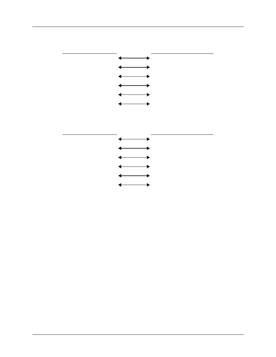
Table 3. TRACER 4106/4206 (DCE) to Terminal (DTE) Diagram (DB-25)
PIN
NAME
PIN
NAME
2
TX
3
TX
3
RX
2
RX
4
RTS
4
RTS
5
CTS
5
CTS
6
DSR
6
DSR
7
GND
7
GND
Table 4. TRACER 4106/4206 (DCE) to Personal Computer (DB-9)
PIN
NAME
PIN
NAME
2
TX
3
TX
3
RX
2
RX
4
RTS
7
RTS
5
CTS
8
CTS
6
DSR
6
DSR
7
GND
5
GND