Installation, Install control panel and wiring – Poweramp POWERSTOP SERIES User Manual
Page 16
14
4111-0014 — July 2013
INSTALLATION
1. Mount the push button control panel (B) so bottom
of control panel-to-dock floor distance (C) is 48 in.
(1219.2 mm).
2. Install electrical disconnect panel (A) if not already
installed. (Provided by others)
3. Install and connect the control wiring to the face
of the building as shown in installation.
4. Connect the dock leveler power cable to the field
wires in the pit junction box. Refer to the electrical
drawings supplied with the dock leveler.
5. After all electrical connections in the vehicle
restraint have been made, test the vehicle restraint
function by following the instructions in the “Put New
PowerStop Restraint Into Service” section on next
page.
Install Control Panel and Wiring
IO ST
-A 11/06
LEVEL
11”
SECTION "A-A"
A
A
7
12
8
9
14
14
6
5
4
1
3
11
10
CONNECT TO BASE END OF RELEASE CYL.
BC
DESCRIPTION
NOTE
RC
CONNECT TO ROD END OF RELEASE CYL.
Capacitor Wiring Detail
M
ot
or
Bl
ue
M
ot
or
Re
d
6
2
13
R.V. SET @
HYDRAULIC SCHEMATIC
105
M
650 PSI
RC
BC
1
1
1431-0011
Connector - 2-Screw
3/8
2
3
1431-0086
Insulated Terminial
16-14 AWG
3
2
2101-0017
Hex Head Capscrew
3/8-16 UNC X 1
4
2
2101-0140
Lock Washer
3/8
5
1
2751-0016
Cover - J-Box
4 X 4
6
1
3051-0058
Capacitor - Motor Start
64-77mF - 330V
7
2
6431-0001
Grommet
1-3/8 OD X 3/4 ID
8
2
9301-0164
Fitting Conn Str Thrd
#4 ORB X #4 JIC
9
1
9391-0009
Powerpac - PowerStop
1PH - 115V - 1/4 HP - 1 GPM
10
1
9392-0045
Cover - PowerStop
B CAD
11
1
9393-0025
Powerpac Mounting Weldment
B CAD
12
2
9904-0097
Hyd Hose Assy - 1/4"100R1 X 24.00
#4 JICF SWIVEL BOTH ENDS
13
1
R513-0050
Wire
16 GA RED X 5.00"
14
2
R598-0090
Split Flex Conduit
1/4" X 9.00"
BILL OF MATERIAL
QTY
ITEM
DESCRIPTION
PART NO.
SIZE
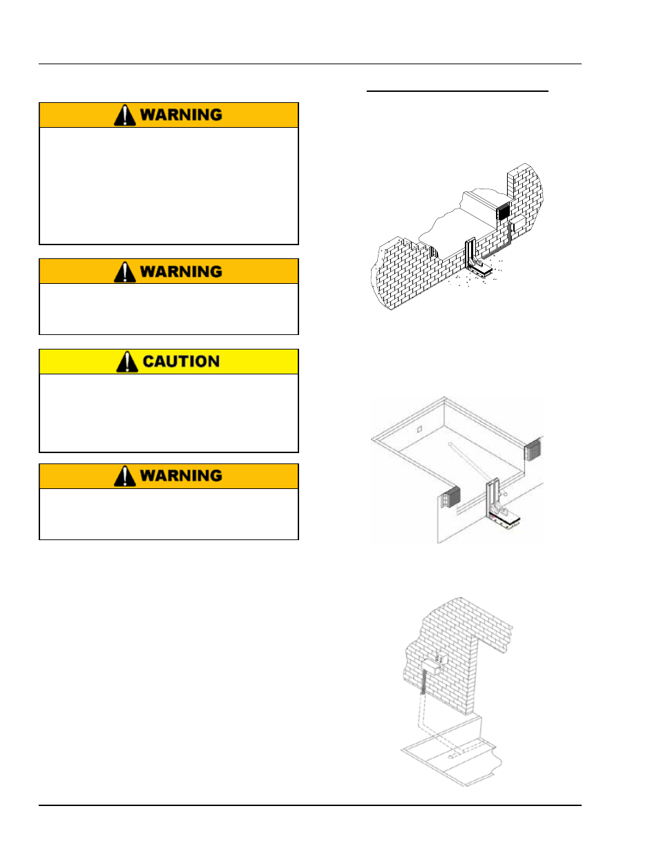
STOP-TITE Overview
STOP-TITE Powerpack
Powerpack
Location Options
For comprehensive installation
instructions of the Automatic
STOP-TITE (STOP-TITE ) read and
understand the Installation
and Operation Manual.
AAL
McGuire.
McGuire
STOP-TITE
STOP-TITE
Coordinate powerpack location and hose
length for proper placement.
Dock Face
Appropriate location when the likelihood of
flooding, snow removal and damage from
trailer/trucks is minimal.
Under The Dock Leveler
When under the dock location is used, make
certain to locate the powerpack where leveler
will not interfere in below dock conditions.
The routing of hydraulic and electrical lines
from the powerpack to the restraint are
best placed through min. 3” PVC (hydraulic)
and 3/4” conduit (electricl) chase during pit
construction.
Inside Building
Locate powerpck to minimize obstruction
potential. Hydraulic and electrical lines
from the Powerpack to the restraint are best
placed through min. 3” PVC (hydraulic) and
3/4” (electrical) chase during pit construction.
AAL
Conduit, flexible or rigid, must be connected between the limit switch on the restraint and the powerpack. Wiring to and
from the restraint must be limited to restraint wires only. Do not run high voltage lines through the same conduit as restraint
wires. Conduit and associated hardware to complete wiring and mounting of powerpack are to be supplied by others.
POWERSTOP Overview
The electrical power must be OFF prior to electrical
installation. For maximum protection, use an OSHA
approved locking device to lock out all power
sources. Only the person installing the equipment
should have the key to unlock the power source.
Failure to follow these instructions may result in
serious personal injury or death.
DO NOT make any final electrical connections until
all welding has been completed. Failure to do this
may result in serious personal injury or death.
If dock leveler is present. Always stand clear of
platform lip when working in front of the dock
leveler. Serious personal injury or death may result.
All electrical work — including the installation of
the disconnect panel, control panel, and final
connections — must be performed by a certified
electrician and conform to all local and applicable
national codes.