Alcatel-Lucent Omni 6600 User Manual
Page 65
OmniSwitch 6600 Family Chassis and Hardware Components
Installing Uplink and Stacking Modules
OmniSwitch 6600 Family Hardware Users Guide
September 2006
page 2-41
Note. The module should slide in easily. Do not force the module into the slot. If any resistance is encoun-
tered, ensure that the module is aligned properly in the card guide and try again.
3
Slide the module back until the backplane connector is inserted in the chassis backplane; the module’s
front panel should be flush with the front of the chassis. Do not force the module into the slot. Otherwise
you can damage the connectors.
4
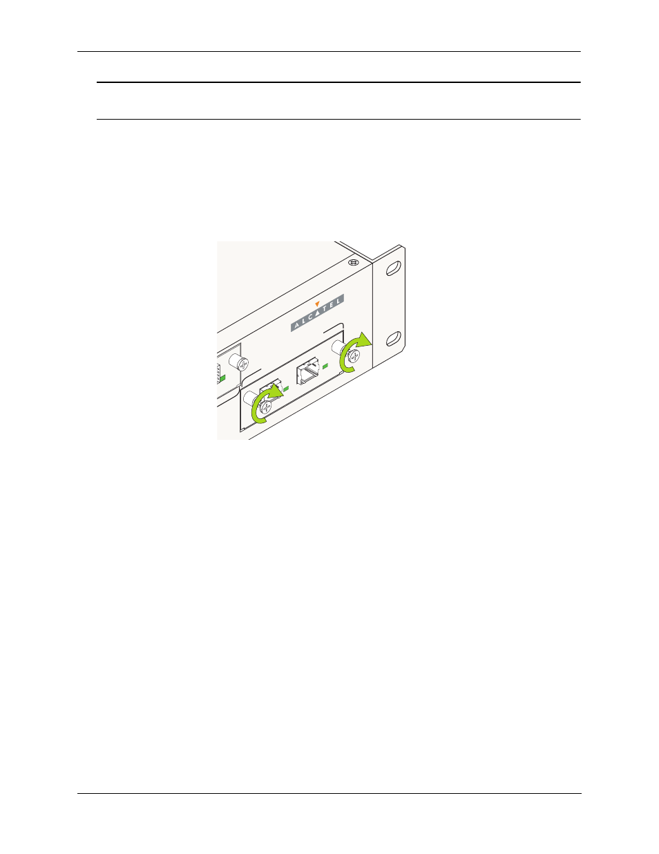
Once the module is firmly seated and flush with the chassis front panel, secure the module by tighten-
ing the two captive screws. Be sure not to overtighten the captive screws. If you use a screwdriver, the
torque used to tighten the screws must not exceed 2.3 inch pounds.
Tightening the Captive Screws
EXP
ANSION/ST
ACKING
51
52
LINK/ACT
LINK/ACT