PASCO OS-8543 Prism Mount User Manual
Page 3
012-07111A
Prism Mount
3
For accurate wavelength measurements, the prism
mount must remain fixed, such that the back face
of the prism is perpendicular to the incoming light
source (Figure 3).
d) From the bottom side of the degree plate,
place a lock washer and wingnut on the
threaded post. Rotate the wingnut to help
secure the mount against the spectrophotometer
table.
4. Attach the Infrared Filter Bracket to the Infrared
Light Sensor (if using the Infrared Light Sensor)
Limited Warranty
PASCO scientific warrants the product to be free
from defects in materials and workmanship for a
period of one year from the date of shipment to
the customer. PASCO will repair or replace, at its
option, any part of the product which is deemed to
be defective in material or workmanship. The
warranty does not cover damage to the product
caused by abuse or improper use. Determination
of whether a product failure is the result of a
manufacturing defect or improper use by the
customer shall be made solely by PASCO
scientific. Responsibility for the return of
equipment for warranty repair belongs to the
customer. Equipment must be properly packed to
prevent damage and shipped postage or freight
prepaid. (Damage caused by improper packing of
the equipment for return shipment will not be
covered by the warranty.) Shipping costs for
returning the equipment after repair will be paid by
PASCO scientific.
Address:
PASCO scientific
10101 Foothills Blvd.
Roseville, CA 95747-7100
Phone:
(916) 786-3800
FAX:
(916) 786-8905
e-mail:
Web site:
www.pasco.com
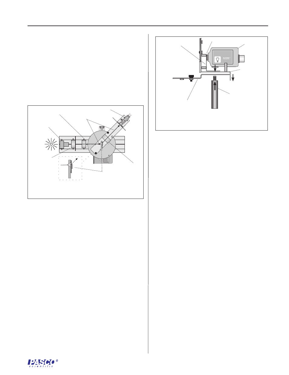
To observe infrared wavelengths, use the Infrared
Sensor instead of the High Sensitivity Light
Sensor.
a) To replace the high sensitivity light sensor, rotate
the threaded post clockwise to loosen the
attachment and remove the light sensor.
b) Place the base of the filter bracket over the front
hole of the light sensor mount, such that the hole
in the bracket base aligns over the front hole on
the mount and the front hole of the light sensor
arm.
c) Place the Infrared Light Sensor over the base of
the bracket. While holding the sensor in place
with one hand, use the other hand to insert the
threaded post from beneath the sensor. Rotate
the post until the sensor holds firmly in place
against the bracket and mount. The glass filter
should fit snugly against the sensor, with the
bracket under the case (Figure 4).
INFRARED SENSOR
CI-6628
Figure 4: Attaching the Infrared Light Sensor and
Filter Bracket
filter bracket
infrared filter
threaded post
light sensor
mount
light sensor arm
light sensor
GAIN
10
100
1
Figure 3: Path of Light Through the Prism
light source
path of light
prism mount
light sensor
focusing lens
collimating lens
collimating slits