Operation – PASCO SE-9638 e-m APPARATUS User Manual
Page 7
2
e/m Apparatus
012-03471E
®
The Helmholtz Coils—The geometry of Helmholtz coils—
the radius of the coils is equal to their separation—provides
a highly uniform magnetic field. The Helmholtz coils of the
e/m apparatus have a radius and separation of 15 cm. Each
coil has 130 turns. The magnetic field (B) produced by the
coils is proportional to the current through the coils (I) times
7.80 x 10
-4
tesla/ampere [B (tesla) = (7.80 x 10
-4
) I].
The Controls—The control panel of the e/m apparatus is
straightforward. All connections are labeled. The hook-ups
and operation are explained in the next section.
Cloth Hood—The hood can be placed over the top of the e/
m apparatus so the experiment can be performed in a lighted
room.
Mirrored Scale—A mirrored scale is attached to the back of
the rear Helmholtz coil. It is illuminated by lights that light
automatically when the heater of the electron gun is pow-
ered. By lining the electron beam up with its image in the
mirrored scale, you can measure the radius of the beam path
without parallax error.
Additional Equipment Needed—
Power Supplies:
6-9 VDC @ 3 A (ripple < 1%) for Helholtz coils
(PASCO Model SF-9584 Low Voltage Power
Supply)
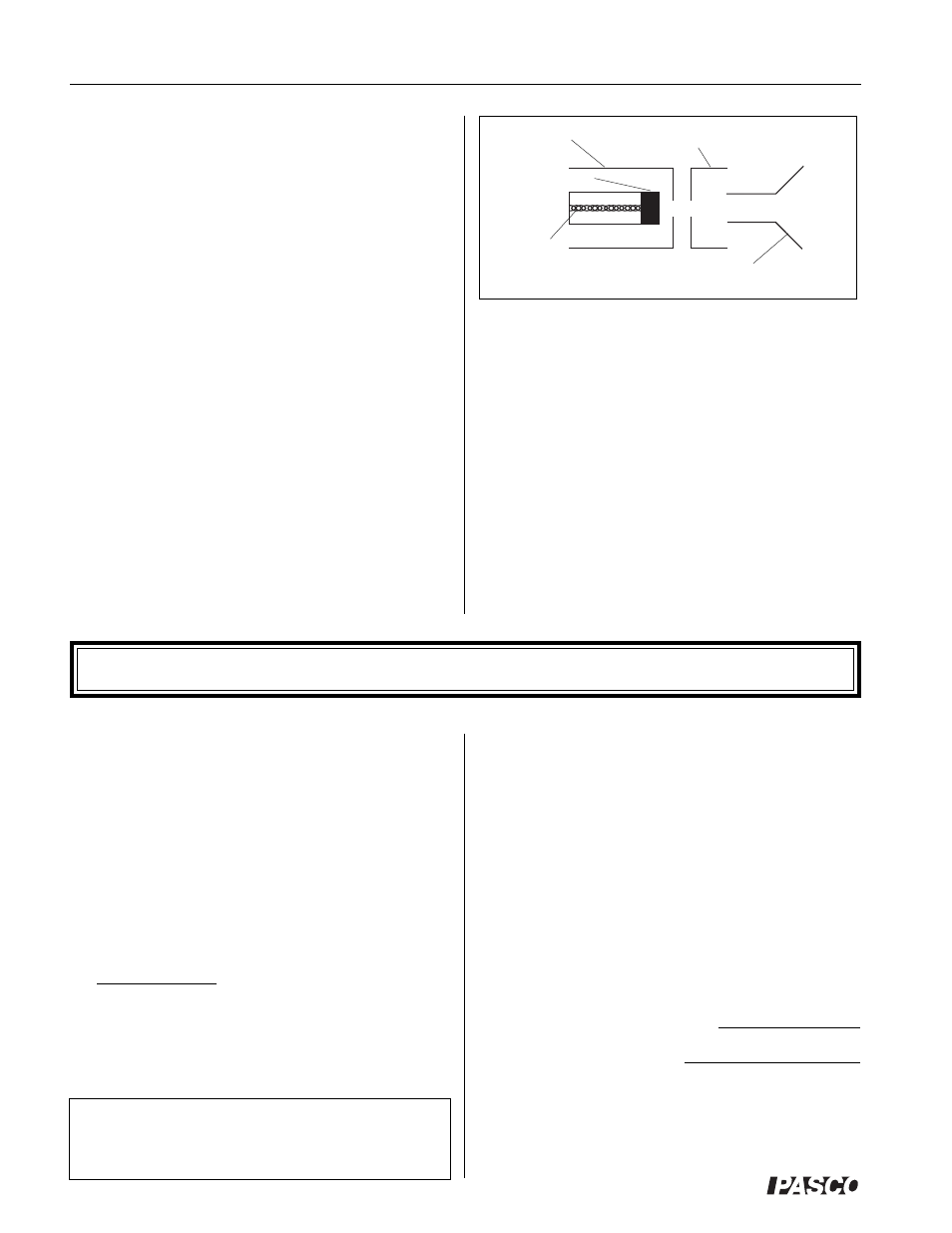
Grid
Cathode
Heater
Deflection Plates
Anode
Figure 3 Electron Gun
6.3 VDC or VAC for filament
150-300 VDC accelerating potential (PASCO
Model SF-9585 High Voltage Power Supply)
Meters:
Ammeter with 0-2 A range to measure current in
Helmholtz coils (such as the PASCO Model SB-
9624 Multimeter)
Voltmeter with 0-300 V range to measure accelerat-
ing potential (such as the PASCO Model SB-9624
Multimeter)
Operation
Measuring e/m
1.
If you will be working in a lighted room, place the
hood over the e/m apparatus.
2.
Flip the toggle switch up to the e/m MEASURE
position.
3.
Turn the current adjust knob for the Helmholtz coils
to the OFF position.
4.
Connect your power supplies and meters to the front
panel of the e/m apparatus, as shown in Figure 4.
5.
Adjust the power supplies to the following levels:
ELECTRON GUN
Heater:
6.3 (VAC or VDC) or as
noted on tube
Electrodes:
150 to 300 VDC
Helmholtz Coils:
6-9 VDC (ripple should be
less than 1%)
CAUTION: The voltage to the heater of the
electron gun should NEVER exceed 6.3 V, unless
noted otherwise on tube. Higher voltages will
burn out the filament and destroy the e/m tube.
6.
Slowly turn the current adjust knob for the Helmholtz
coils clockwise. Watch the ammeter and take care that
the current does not exceed 2 A.
7.
Wait ten minutes for the cathode to heat up. When it
does, you will see the electron beam emerge from the
electron gun and it will be curved by the field from the
Helmholtz coils. Check that the electron beam is
parallel to the Helmholtz coils. If it is not, turn the
tube until it is. Don’t take it out of its socket. As you
rotate the tube, the socket will turn.
8.
Carefully read the current to the Helmholtz coils from
your ammeter and the accelerating voltage from your
voltmeter. Record the values below.
Current to Helmholtz coils = I =
Accelerating voltage = V =
9.
Carefully measure the radius of the electron beam.
Look through the tube at the electron beam. To avoid
parallax errors, move your head to align the electron
beam with the reflection of the beam that you can see