Specifications assembly, Figure 4: laser beam fine adjustment, Manuf actured b y – PASCO OS-8475 DIODE LASER User Manual
Page 2: Man ufactured by, Pasco advanced optics bench (not included), Input jack (9vdc) adjustment screws mount slots
®
Diode Laser for
Optics Systems
012-12250A
2
SPEE
D OF LIGH
T
RED
DIO
DE
LA
SER
OS-8475
AVO
ID EX
POS
URE
LAS
ER L
IGHT IS
EM
ITTED
FRO
M TH
IS AP
ERTU
RE
®
1010
1 Fo
othil
l Blv
d.
Rose
ville
, CA
. 957
47 U
SA
OS-8475
DIODE
LASER
FOR
OPTICS SYSTEMS
Manuf
actured b
y:
10101
Footh
ill Blvd
.
Rosev
ille, C
A 9574
7 USA
®
SPEE
D O
F LIG
HT
RED
DIO
DE L
ASE
R
OS-8475
AVOID EXPOSURE
LASER LIGHT IS EMITTED
FROM
THIS APER
TURE
®
10101
Footh
ill Blv
d.
Rosev
ille, C
A. 957
47 US
A
SPEED
OF LIGH
T
RED
DIO
DE
LA
SER
OS-8475
AVOID EXPOSURE
LASER LIGHT IS EMITTED
FROM
THIS APER
TURE
®
10101 Foothill Blvd.
Rose
ville
, CA.
95747 USA
OS-8475
DIODE
LASER
FOR
OPTICS SYSTEMS
Man
ufactured
by:
10101
Footh
ill Blvd
.
Rosev
ille, C
A 9574
7 USA
®
OS-8528A
DIODE LASER
PASCO
OPTICS SYSTEMS
9 VDC 500m
A
GN
D
3.5m
m
HORIZO
NTAL
ADJUS
T
VER
TICAL
ADJUST
ON
OFF
POW
ER
+9V
DC
RED LASER DIODE
Wavelength:
650 nm
Output:
<1
mW
OS-8475
DIODE
LASER
FOR
OPTICS SYSTEMS
Manu
factu
red b
y:
10101 F
oothill Blvd.
Rose
ville
, CA 95747 USA
®
Specifications
Assembly
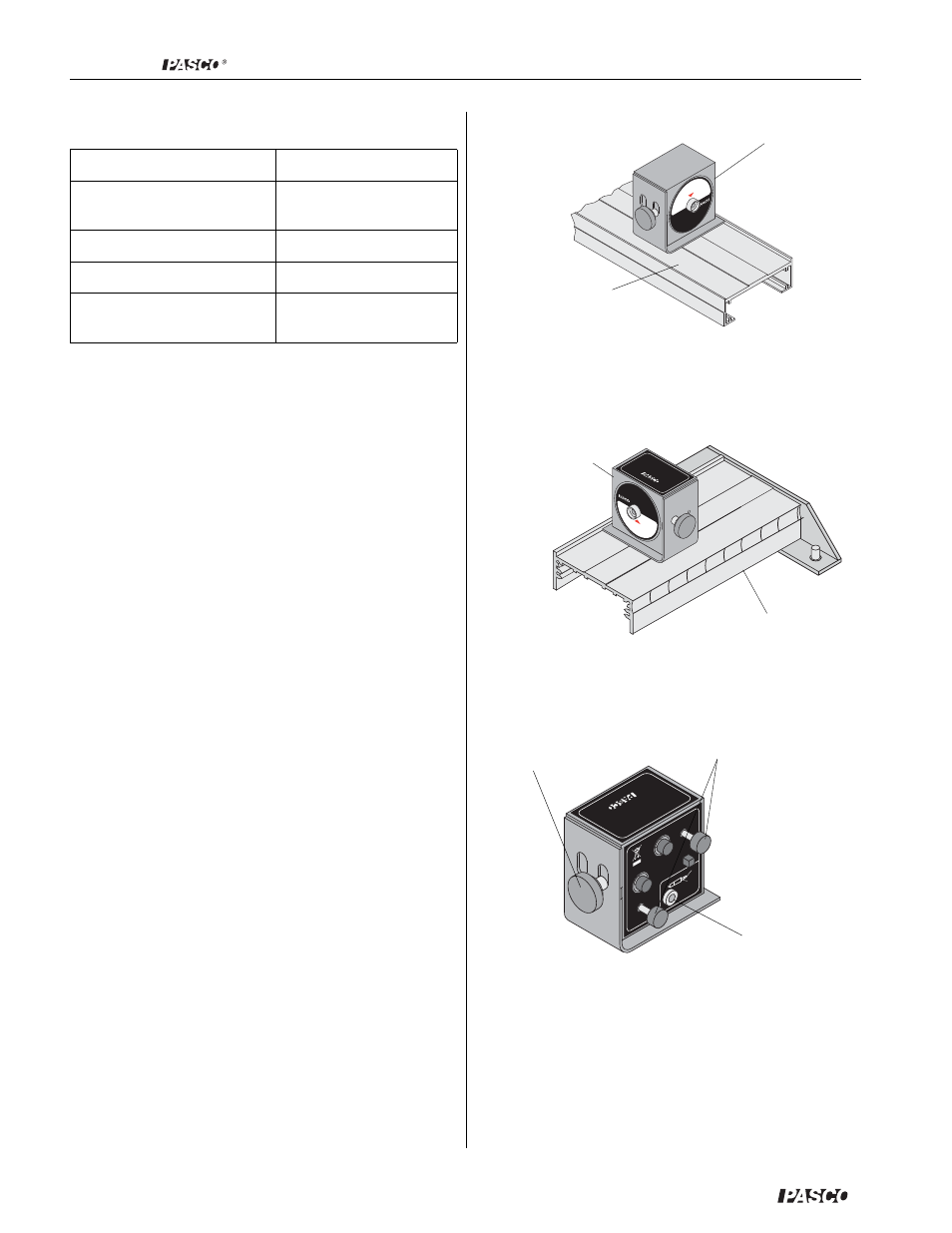
1. Determine the configuration of your experiment
and the location in which the Diode Laser will be
set up and adjust the orientation of the Diode Laser
accordingly. Make sure the face of the laser diode
assembly is relatively perpendicular to the surface
of your optics bench. This will minimize the
amount of fine adjustment you may need to per-
form in step 4. Tighten the thumbscrew to secure
the laser diode module.
2. Place the “alignment edge” of the Diode Laser
against the alignment rail of your PASCO optics
bench. See Figures 2 and 3.
3. Plug the 9VDC adapter phone plug into the back of
the laser and turn on the laser.
4. If necessary, use the adjustment screws to align the
laser beam from left-to-right and up-and down. See
Figure 4.
5. When using with the Laser Slits, OS-8529, slide the
Laser Diode to the top of the slots on the mount
Classification
Class II Laser
Wavelength
532 nm (green)
650 nm (red)
Maximum Output
<1 mW
Divergence
<2 mrd
Beam Diameter at
aparture
3 mm
Figure 2: Laser Diode Setup foPASCO Introductory
Optics bench
PASCO Advanced
Optics bench
(not included)
Figure 3: Laser Diode Setup for
PASCO Advanced Optics bench
OS-8475
Laser Diode
PASCO Introduc-
tory Optics bench
(not included)
OS-8475
Laser Diode
Figure 4: Laser Beam Fine Adjustment
input jack
(9VDC)
adjustment
screws
mount slots