Operation, Manual aut o – PASCO WA-9613 Driver_Detector Coils User Manual
Page 2
2
Driver/Detector Coils
012-03479C
WA-9611
SONOMETER
KEEP WEIGHTS AS NEAR TO FLOOR
AS POSSIBLE IN THE EVENT THE
SONOMETER WIRE SHOULD BREAK
CAUTION!
1.75 kg MAXIMUM
LOAD ON LEVER
BK PRECISION
200 Mhz OSCILLISCOPE
MODEL
2 1 2 0
INTENSITY
FOCUS
TRACE NOT ATION
TRIG LEVEL
COUPLE
SOURCE
SLOPE
- Y
TIME/DI
V
X-POS
VAR
VAR
VAR SWEEP
CAL
CAL
m
V
V
CH 1
VOLTZ/DIV
CH 2
VOLTZ/DIV
CAL
m
V
V
VERTICAL MODE
PULL XS
PULL XS
CH 2
∞
CH 1
∞
AC
DC
AC
DC
AC
CH1
CH2
ALT
EXT
POS
POS
NORM
EXT
CH1
CH2
NORM
EXT
CH1
CH2
MANUAL
AUT
O
T X-
YT X-
Y
LINE
CAL
EXT CH4
POWER
200V
MAX
400V
MAX
400V
MAX
-
+
+
-
T T
L H I
Ω
G
N D
L O
Ω
M I
N
R A
N G E
A D J U
S T
M
A X
O U T P
U T
F R E Q U E N
C Y
A M P L I T U
D E
P I - 9 5 8 7 B
D I G I T AL FUNCTION
G E N E R A TOR -
A M P L I F I E R
H E
R T Z
WA V E F O
R M
I N P
U T
G N D
E X T E R N
A L
DETECT
OR
W A-9613
DRIVER
WA-9613
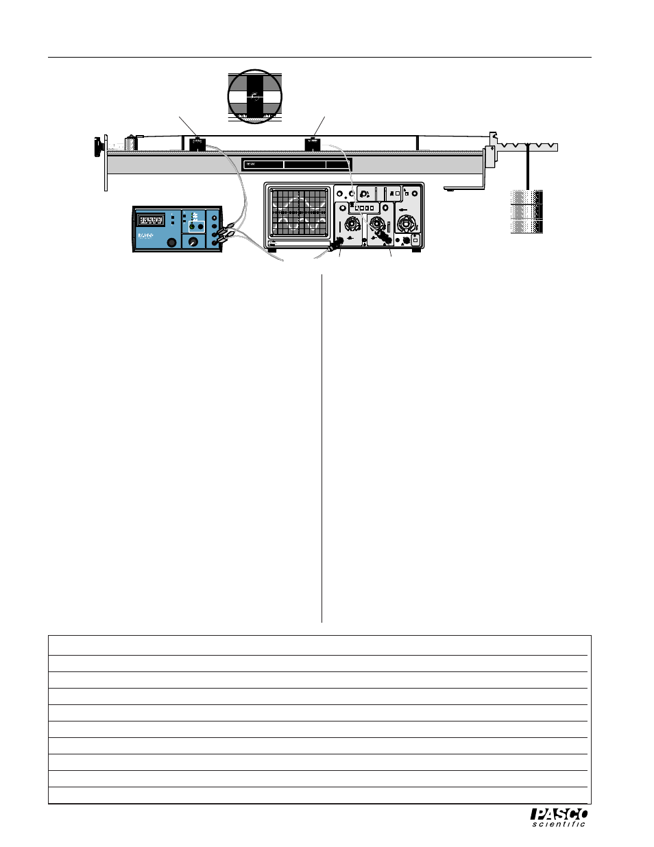
Operation
To connect the Driver/Detector Coils to a function
generator and oscilloscope:
➀
Connect the Driver and Detector Coils to the function
generator and oscilloscope as shown in the diagram.
Connect the Driver Coil directly to the output of the
PASCO PI-9587B Digital Function Generator. Connect
the Detector Coil directly to channel two of an oscillo-
scope that has a BNC connector. You can use banana
plug patch cords and a BNC-to-banana plug adapter to
connect the output of the function generator to channel
one of an oscilloscope that has a BNC connector.
➁
Set the gain on channel-one of the oscilloscope to 5
mV/div. Adjust the oscilloscope so it triggers on the
signal from the function generator.
➂
Position the Driver Coil approximately 5 cm from one
of the bridges of the Sonometer.
Depending on the wave pattern you are trying to pro-
duce, you might want to place the driver at some other
position. It will drive the string best if it is placed at an
antinode of the wave pattern.
➃
Position the Detector midway between the bridges ini-
tially, though for some patterns, you may want to re-
position it to best pick up the signal. As with the
Driver Coil, it works best when positioned near an an-
tinode of the wave pattern.
➄
Set the function generator to produce a sine wave. Set
the frequency to a value between 100 and 200 Hz. Ad-
just the amplitude to about 5 V (approximately half of
maximum). Slowly vary the frequency of the function
generator output. When you reach a resonant fre-
quency, you should see the motion of the string and
the sound produced by the vibrating string should be a
maximum. The wave pattern shown on the oscillo-
scope should become a clean sine wave. If you can’t
see or hear the string, raise the amplitude of the func-
tion generator output and try again.
Using the Driver/Detector Coils with a PASCO
Computer Interface
There are several ways to use the Driver/Detector Coils with
a PASCO Computer Interface. The method you use depends
on the kind of computer, the interface (e.g., CI-6500, CI-6550,
etc.), the device to control the driver coil, and whether you
wish to do frequency analysis (Fast Fourier Transform or
FFT) of the standing waves produced by the driver coil.
Computer
Interface
Device to drive coil
Software
FFT?
Apple II
AI-6501
Power Amplifier
Power Amplifier (Apple II)
no
Apple II
AI-6501
function generator
Data Monitor (Apple II)
no
DOS - PC
CI-6500
Power Amplifier
Power Amplifier (MS-DOS)
no
DOS - PC
CI-6500
function generator
Data Monitor (MS-DOS)
yes
Macintosh
CI-6550
Power Amplifier
Science Workshop (Mac)
yes
Macintosh
CI-6550
function generator
Science Workshop (Mac)
yes
Windows - PC
CI-6565
Power Amplifier
Science Workshop (Windows)
yes
Windows - PC
CI-6565
function generator
Science Workshop (Windows)
yes
Windows - PC
CI-6500
function generator
Data Monitor (Windows)
yes
Function Generator
Oscilloscope
Driver Coil
Detector coil
Channel 2
Channel 1 (trigger)