PASCO TD-8572 HEAT ENGINE_ GAS LAW APPARATUS User Manual
Page 16
Heat Engine/Gas Law Apparatus
012-06014C
12
®
Hot
Cold
HEAT ENGINE
GAS LAW APPARATUS
Piston Dia.:
32.5mm±0.1
TD-8572
CAUTION:
Max. Pres.: 345kPa. Use Gases Only
DO NOT Immerse in any Liquid
DO NOT Lubricate Piston or Cylinder
Pressure Port Mating Connector:
PASCO Part No. 640-021
Piston&Platform
Mass: 35.0g±0.6
m
If the temperature of the air trapped inside the cylinder, hose, and can is increased, then its
volume will increase, causing the platform to rise. Thus, you can increase the volume of the
trapped air by moving the can from the cold to the hot reservoir. Then, when the apple has
been raised through a distance y, it can be removed from the platform. The platform should
then rise a bit more as the pressure on the cylinder of gas decreases a bit. Finally, the volume
of the gas will decrease when the air chamber is returned to the cold reservoir. This causes
the piston to descend to its original position once again. The various stages of the mass lifter
cycle are shown in Figure 5.3.
Before taking data on the pressure, air volume, and height of lift with the heat engine, you
should set it up and run it through a few cycles to get used to its operation. A good way to
start is to fill one container with room temperature water and another with hot tap water or
preheated water at about 60–70°C. The engine cycle is much easier to describe if you begin
with the piston resting above the bottom of the cylinder. Thus, we suggest you raise the
piston a few centimeters before inserting the rubber stopper firmly in the can. Also, air does
leak out of the cylinder slowly. If a large mass is being lifted, the leakage rate increases, so
we suggest that you limit the added mass to something between 100 g and 200 g. After
observing a few engine cycles, you should be able to describe each of the points a, b, c, and
d of a cycle carefully, indicating which of the transitions between points are approximately
adiabatic and which are isobaric. You can observe changes in the volume of the gas directly
and you can predict how the pressure exerted on the gas by its surroundings ought to change
from point to point by using the definition of pressure as force per unit area.
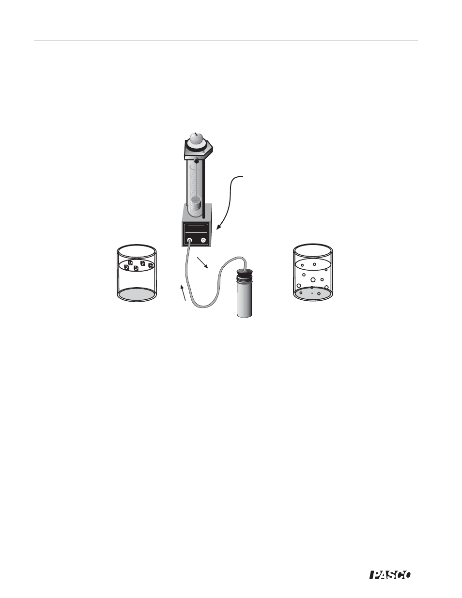
Figure 5.2. A schematic diagram of the incredible mass lifter heat engine.
Close the shut-off valve
on the tubing from the
unused port.
The Incredible Mass Lifter Engine
The heat engine consists of a hollow cylinder with a graphite piston that can move along the axis of the
cylinder with very little friction. The piston has a platform attached to it for lifting masses. A short
length of flexible tubing attaches the cylinder to an air chamber (consisting of a small can sealed with a
rubber stopper that can be placed alternately in the cold reservoir and the hot reservoir. A diagram of
this mass lifter is shown in Figure 5.2.