Operation, Clamp the photogate head to the support rod – PASCO ME-9204B ACCESSORY PHOTOGATE User Manual
Page 2
2
Accessory Photogate
012-06375A
®
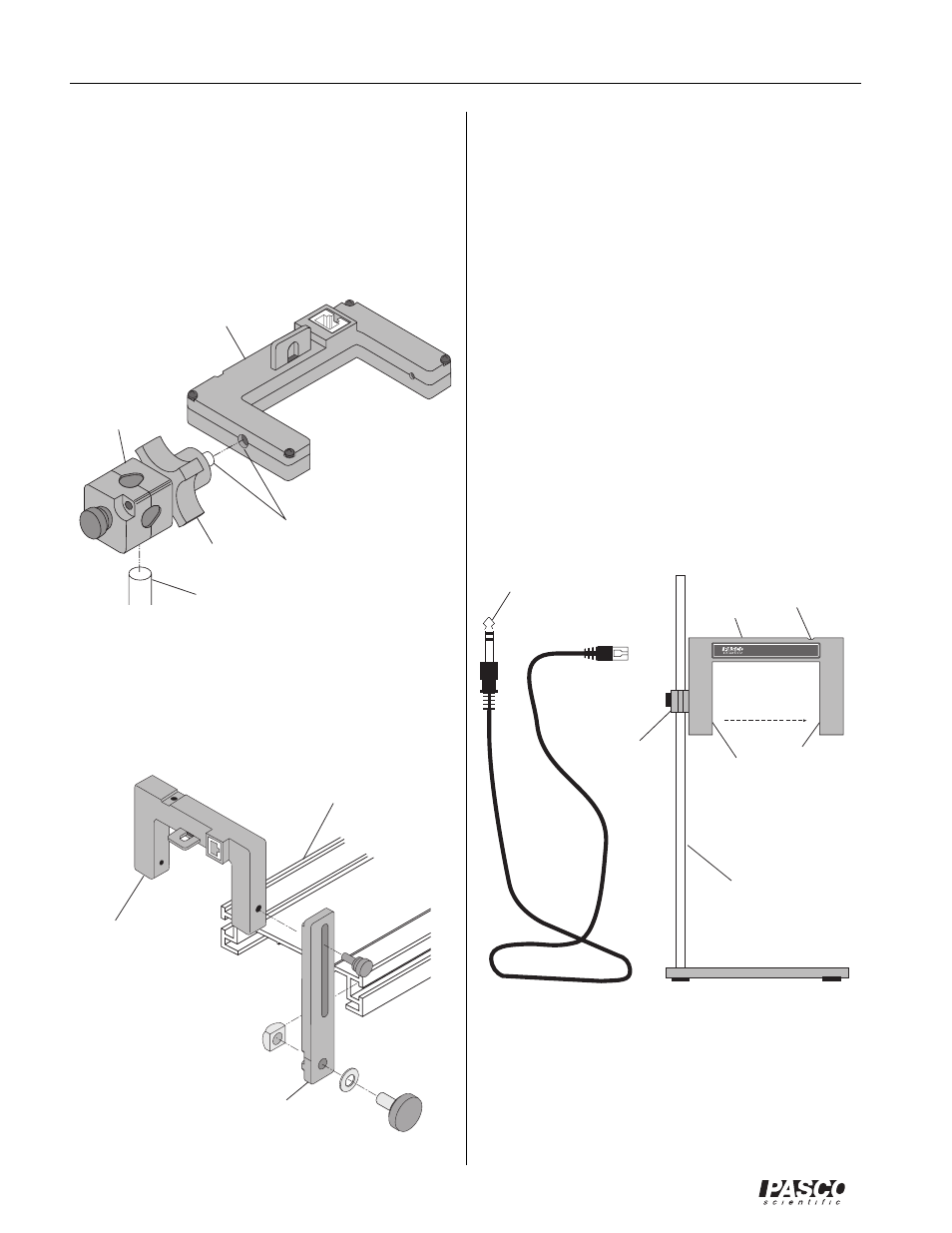
The Photogate Head can be mounted on a support rod of
up to half inch in diameter by attaching a PASCO
ME-8744 Adjustable Angle Clamp. It is necessary to re-
move the “mobile” rod clamp from the clamp assembly
and secure the “fixed” part of the clamp assembly to the
1/4-20 thread provided in the photogate housing opposite
the side of the small rod clamp. Rotate the equipment to
the correct orientation and then secure it with the locking
knob.
The Photogate Head can also be attached to the side of a
PASCO Dynamics Track with an IDS mounting bracket
(part of PASCO ME-9471 IDS Photogates and Fences).
It is necessary to remove the small rod clamp from the
photogate housing.
Operation
Clamp the Photogate Head to the support rod.
Position the photogate so the object to be timed will
pass through the photogate, blocking the beam. (See
Figure “Photogate with Pendulum”). To minimize
parallax error, pass the object as close to the detector
as possible, with the line of travel perpendicular to the
beam. Loosen the clamp screw to change the angle or
height of the photogate.
Plug the RJ12 phone plug from the cable assembly
into the modular phone jack on the photogate housing.
Plug the stereo phone plug at the other end of the
cable assembly into the timer, adapter cable, or inter-
face.
Test the operation of the photogate by watching the
LED when the beam is blocked.
Photogate
Head
Dynamics
Track
IDS mounting
bracket
small rod
clamp
detector
emitter
stereo
phone plug
(to timer)
LED: ON when
beam is blocked
1/4”dia
support rod
base
RJ12 phone plug
(to modular phone
jack on photogate)
Photogate
Head
Photogate
Head
Adjustable
Angle Clamp
(“fixed”)
1/2” diameter
support rod
1/4-20 thread
Accessory Photogate
®
PHOTOGATE HEAD
ASSEMBLY NO.003-06268
locking
knob