Electronic circuitry and internal operation, Thermistor description, Is rt=-v – PASCO CI-6527A Thermistor Sensor User Manual
Page 2: Where v, Is 10v reference voltage. r, The normalized resistance r, And r
Thermistor Sensor
012-08463B
2
®
Electronic Circuitry and Internal
Operation
10K Thermistor Circuit - The 10K thermistor circuit
uses a precision voltage source and voltage divider to
determine the thermistor’s resistance. The thermistor
(Rt) is one resistor, and a 13K resistor (R
ref
) is the
other in a two-resistor voltage divider network. In the
sensor housing, the reference resistor, voltage
regulator, and filter capacitor comprise the remainder
of the network. The relationship of the 10K
thermistor’s resistance (Rt) to voltage output (V
out
) is
Rt=-V
out
*R
ref
/(V
ref
-V
out
)
where V
ref
is 10V reference voltage. R
ref
is 13 Kohms.
The normalized resistance is R10=Rt/10,000.
100K Thermistor Circuit - The 100K thermistor
circuit outputs a positive voltage that is directly
proportional to the resistance of the resistor. The range
of resistance over which the sensor functions is 0 to
360K ohms. This resistance range maps into a 0 to 10
VDC output from the sensor. The relationship is Rt =
36,000*V
out
. The normalized resistance R
100
=R
t
/
100,000. The Steinhart-Hart equation is used to
convert from resistance to temperature, where T, the
temperature in degrees Celsius is
and R
100
is the normalized resistance of the thermistor
in ohms.
0
20
40
60
80
100
120
0
100,000
200,000
300,000
400,000
Resistance(ohms)
T
emp
erat
u
re(
ºC
)
Thermistor Description
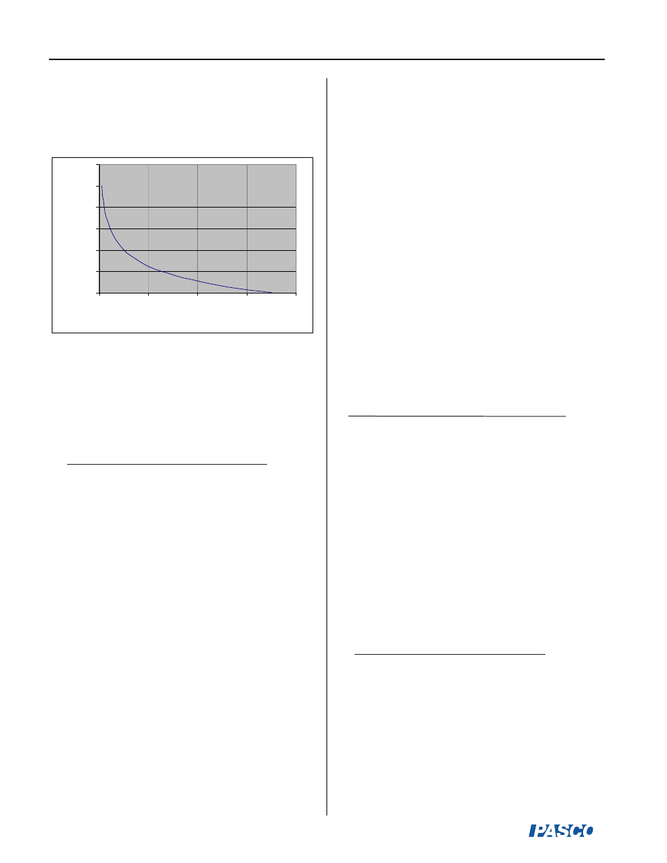
Figure 1 illustrates a typical resistance vs. temperature
curve for a 100K ohm thermistor.
Thermistors have a negative temperature coefficient.
As the temperature increases, the resistance of the
thermistor decreases. The Steinhart-Hart equation is
used to convert from resistance to temperature, where
T in degrees Celsius is
1
(
8.25x10
-4
+2.05x10
-4
.ln(R100) + 1.14x10
-7
.ln(R100)
3
)
-273.15
and R
100
is the resistance in ohms.
10K thermistor - The 10K thermistor wire plugs into
the 3.5 mm jack and has an output voltage ranging
from 0 to -10 volts. The DataStudio software converts
the voltage to resistance and temperature.
100K thermistor - The 100K thermistor plugs into the
BNC jack and outputs a voltage ranging from 0 to +10
volts. The DataStudio software converts the voltage to
resistance and temperature.
The Steinhart equation is used to convert from
resistance to temperature, where T, the temperature in
degrees Celsius is
and R
10
is the normalized resistance of the thermistor
in ohms.
Figure 1
1
(
3.35x10
-3
+2.56x10
-4
.ln(R10) + 2.38x10
-6
.ln(R10)
2
+ 8.37x10
-8
.ln(R10)
3
)
-273.15
1
(
8.25x10
-4
+2.05x10
-4
.ln(R100) + 1.14x10
-7
.ln(R100)
3
)
-273.15
When the Thermistor Sensor is connected to a
ScienceWorkshop interface, DataStudio determines
which thermistor, the 10K or the 100K, is connected to
the unit by the polariy of the V
out
signal, as long as the
thermistors are connected appropriately (10K to the
stereo jack and 100K to the BNC connector).