Diamond Products CC7074 User Manual
Page 25
22
3. Reinsert the mesh strainer and retighten the strainer
cap to the filter.
Speed Control Lever
Adjusting the Lever Tension
Adjust the tension felt in the speed control lever, when
moving the lever forward and backward, to the desired
setting as necessary.
1. Remove front access panel.
2. Remove the grease cap from the pivot housing.
3. Loosen the jam nut on the opposite side of the
speed control frame using provided wrench.
4. Use the Allen wrench provided to adjust the
shoulder screw.
5. Retighten the jam nut.
6. Move the speed control lever forward and backward
to test the lever tension. Readjust the shoulder
screw/jam nut if desired.
7. Secure the grease cap to the pivot housing.
8. Replace access panel and retighten.
Adjusting the Spring Plungers
Adjust the spring plungers if the speed control lever feels
floppy or loose when moving the lever forward and
backward, or when the lever is hard to place into or out
of the Stop position.
1. Loosen both hex nuts from the speed control tube.
2. Screw the spring plungers slightly out to let the
speed control lever move easily into and out of the
Stop position. Screw the spring plungers slightly in
to let the speed control lever move forward and
backward firmly in the forward/reverse slot.
3. Retighten both hex nuts to secure.
Inner Blade Flange
Figure 16: Inner Flange
Installing the Inner Blade Flange
1. Inspect the inner flange for damages. Clean or
replace damaged components as necessary.
2. Align the flange with the blade shaft key and place
the flange onto the blade shaft.
3. Apply Loctite 262 (red) or an equivalent to the
setscrew threads.
4. Tighten the setscrew(s) into the back of the inner
flange to secure.
Removing the Inner Blade Flange
1. Remove
the
setscrew(s)
from the back of the inner
flange using an Allen wrench.
2. Carefully remove the flange from the blade shaft.
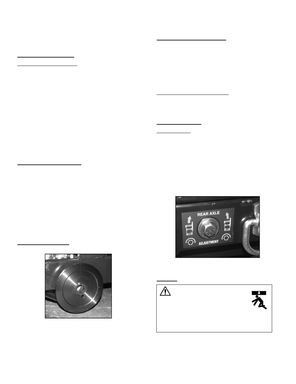
Drive Alignment
Drive Alignment
Adjust the rear axle when the saw’s drive alignment is off
(saw will not cut in a straight line). Note: The rear axle
does not have to be adjusted for straightness; it can also
be adjusted based on the specifications of the cutting
job.
1. Turn the tap bolt clockwise using the provided
wrench to adjust the drive alignment toward the
right, or counterclockwise to adjust the drive
alignment toward the left.
Figure 17: Adjustment Bolt
Wheels
WARNING
Raise the saw to a proper height for
access when working underneath
the saw. Use chocks to block the
wheels, and fit blocks or jacks under the frame
edges at the front and back of the frame.