Final heater assembly – Detroit Radiant Products Company SV Series User Manual
Page 23
Tube Heater General Manual
23
3.0
Installation
•
Baffle Assembly
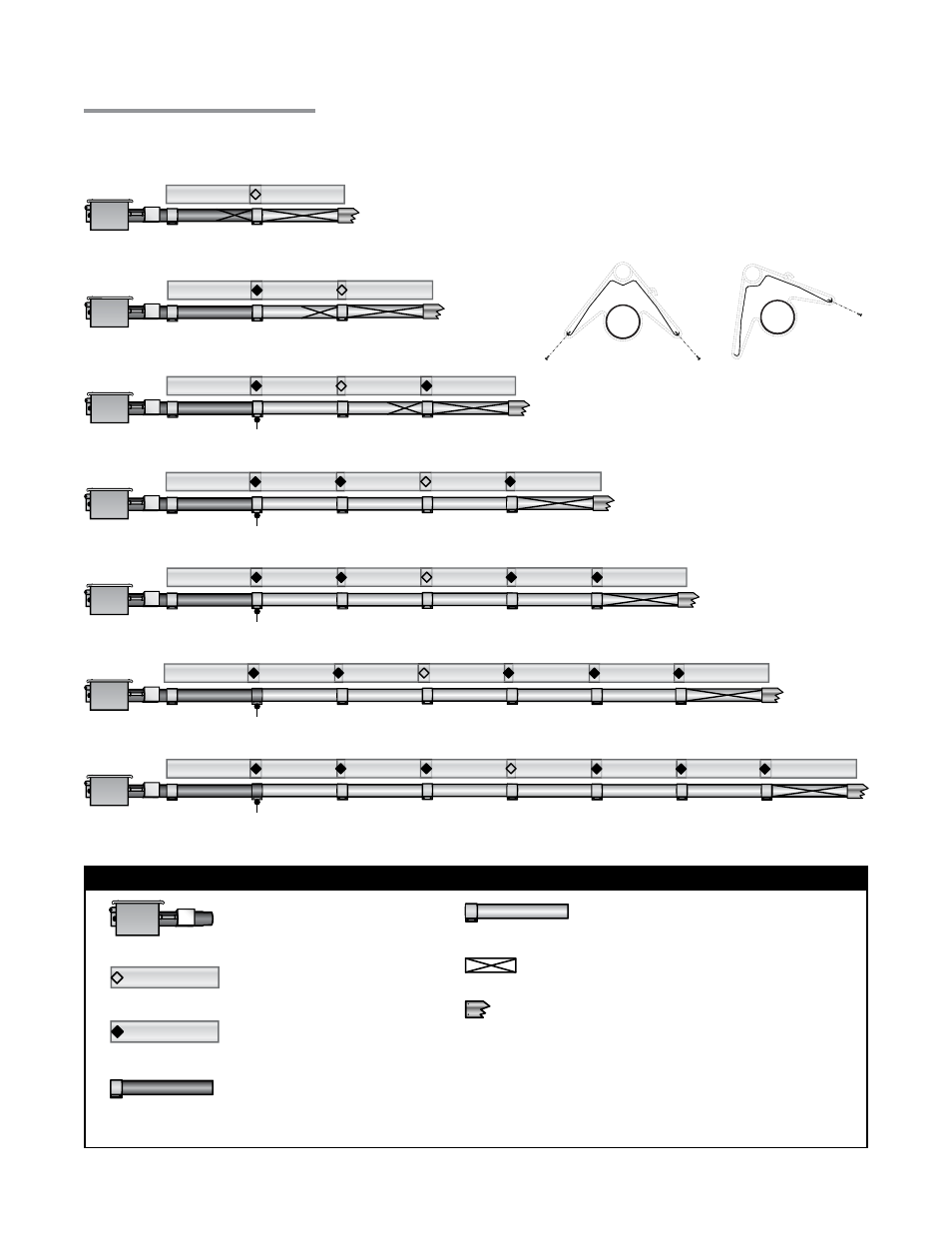
Chart 3.6
Tube Installation Sequence, Baffle Location and Secured Joints for Reflectors
30 Foot
40 Foot
*
*
*
*
*
Burner Control Box
w/16 in. Burner Tube
Key
Expansion Joint on
Reflectors
Secured Joint on
Reflectors (see note)
Primary Combustion
Chamber with Clamp
Radiant Tube
Exchanger with Clamp
Baffle Location
Secure vent material to exchanger with three #8
sheet metal screws. Seal with high temperature
silicone sealant. Do not use tube clamp.
20 Foot
Final Heater Assembly
* A secondary combustion chamber is installed as the
second tube downstream from the burner control box on
150,000 to 200,000 BTU/h models. Refer to the Series
Insert Manual for installation requirements.
50 Foot
60 Foot
70 Foot
80 Foot
Stainless steel clamp on 150,000 to 200,000
BTU/h models (P/N: TP-220).
Stainless steel clamp on 150,000 to 200,000
BTU/h models (P/N: TP-220).
Stainless steel clamp on 150,000 to 200,000
BTU/h models (P/N: TP-220).
Stainless steel clamp on 150,000 to 200,000
BTU/h models (P/N: TP-220).
Stainless steel clamp on 150,000 to 200,000
BTU/h models (P/N: TP-220).
NOTE: When securing joints on reflectors which
are rotated on an angle from horizontal, secure
joint only on top side of reflector to allow for
sufficient heater expansion and contraction.
1 to 45° Mounting Angle
0° Mounting Angle