Detroit Radiant Products Company SV Series User Manual
Page 18
* 5EA-SUB may only be ordered at the time of heater
production. Field corrections require two (2) TR-60 packages.
Tube Heater General Manual
18
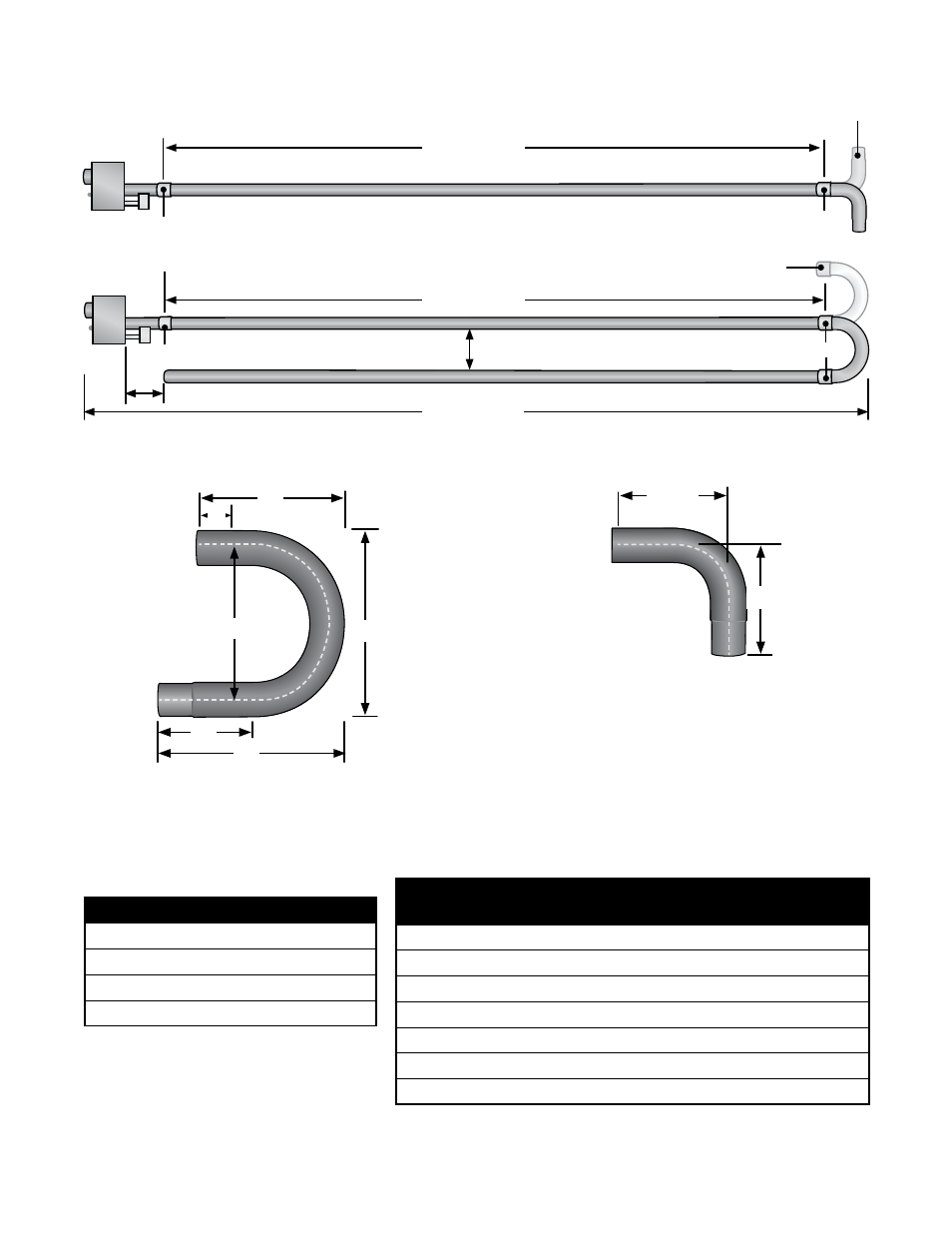
Figure 3.12
•
Elbow and U-Bend Clearances
Chart 3.3
Minimum Distance From Burner
Control Box to Elbow or U-bend
Accessory Fitting
Dimension A
U-Bend can be set in both directions
12”
Figure 3.13
•
U-Bend and Elbow Dimensions
Chart 3.4
Overall Dimensions for Heaters Configured
With U-Bend (P/N: TF1B)
3.0
Installation
•
Optional Elbow or U-Bend Accessory Configuration
Elbow can be set
in both directions
Tube Clamp
Tube Clamp
Dimension A
Dimension B
P/N: TF1B (4”)
P/N: E6 (4”)
8”
Model Tube
Length
Dimension B
Notes
20 ft.
13’-0” / 156”
N/A
30 ft.
17’-8” / 212”
Requires P/N: 5EA-SUB *
40 ft.
22’-8” / 272”
N/A
50 ft.
27’-4” / 328”
Requires P/N 5EA-SUB *
60 ft.
32’-4” / 388”
N/A
70 ft.
37’-0” / 444”
Requires P/N 5EA-SUB *
80 ft.
42’-0” / 504”
N/A
Model MBH Range
Dimension A
50 - 100
10 ft.
110 - 125
15 ft
130 - 175
20 ft.
200
25 ft.
16”
16”
6”
20”
10”
20”
Tube Clamp
Tube Clamp
12.5”
12.5”