Warning, Wiring, Figure 2.1 • field wiring diagrams – Detroit Radiant Products Company DET3 Series User Manual
Page 7
7
DET3
Series
2.0
Installation • Wiring
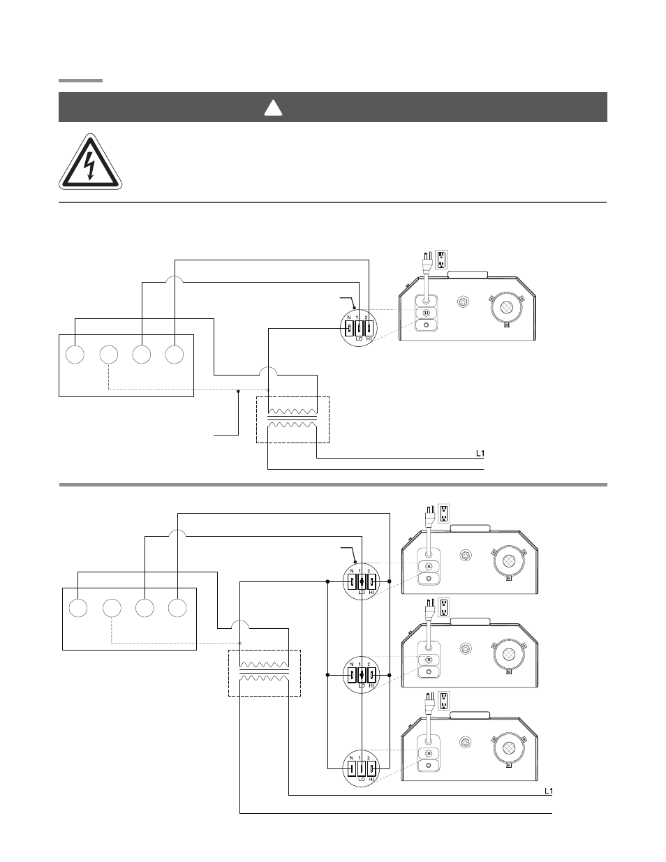
Wiring
Figure 2.1
•
Field Wiring Diagrams
A. Single Heater, Single Thermostat.
B. Multiple Heaters, Single Thermostat.
120VAC
24VAC
120VAC Power
(observe polarity)
NOTE: If optional yellow control cord
is installed then the following wire
colors apply:
Neutral = green
Low = white
High = black
Three 1/4 in.
spade terminals
as supplied
DET3 BURNER BOX
Additional wire needed
for thermostats that
require constant power.
THERMOSTAT
24VAC
N
Low
High
EXTERNAL TRANSFORMER
(field supplied)
To 120VAC grounded outlet.
N
120VAC Power (observe polarity)
NOTE: If optional yellow control cord is
installed then the following wire colors apply:
Neutral = green
Low = white
High = black
DET3 BURNER BOX
Additional wire needed for thermostats
that require constant power.
24VAC
N
Low
High
EXTERNAL TRANSFORMER
(field supplied)
THERMOSTAT
To 120VAC grounded outlet.
To 120VAC grounded outlet.
To 120VAC grounded outlet.
N
DET3 BURNER BOX
DET3 BURNER BOX
Three 1/4 in.
spade terminals
as supplied
120VAC
24VAC
WARNING
!
Electric Shock
Field wiring to the tube heater must be connected and grounded in accordance with national,
state, provincial, local codes and to the guidelines in the Tube Heater General Manual and Series
Insert Manual. In the United States refer to the most current revisions to the ANSI/NFPA 70
Standard, and in Canada refer to the most current revisions to the CSA C22.1 Part I Standard.