Warning, Clearance to combustibles, Sa mpl e sa mpl e – Detroit Radiant Products Company DET3 Series User Manual
Page 4: Installer, F/n: lltb004, Input btu/h, For use with, Aluminized tube, Avoid equipment failure
4
DET3
Series
1.0
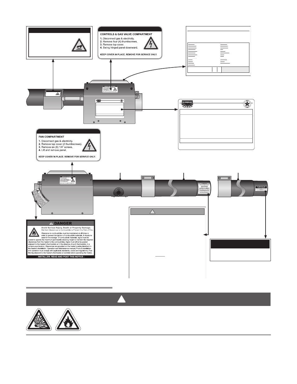
Safety • Safety Labels and Locations • Clearance to Combustibles
Clearance to Combustibles is defined as the minimum distance that must exist between the tube surface,
or reflector, and any combustible items (see Figure 1.1). It also pertains to the distance that must be
maintained from moving objects around the tube heater.
Clearance to Combustibles
®
DETROIT RADIANT PRODUCTS COMPANY
21400 HOOVER ROAD - WARREN, MI
RE-VERBER-RAY INFRA-RED RADIANT TUBE HEATER
FOR OUTDOOR USE AND INDOOR (Non-Residential) INSTALLATION ONLY.
Class IIIA Permanent Label
(586) 756-0950
- www.drp-co.com
Volts AC:
AMPS - Starting:
AMPS - Running:
Combustion Chamber:
120V - 60Hz
1.7
1.1
4” Black Coated Aluminized
DESIGN COMPLIES WITH:
ANSI Z83.20b-2004-GAS FIRED LOW INTENSITY INFRA-RED HTR.
Manifold Pressure:
Maximum Inlet Pressure:
Minimum Inlet Pressure:
3.5 in.
14 in.
5.0 in.
W.C.P.
W.C.P.
W.C.P.
Serial No.: 0807XXXXXXXXXX 0001
MODEL NO.
DET-40-125N(-3)
Heater Type
Minimum Mounting Angle:
Maximum Mounting Angle:
C1
0
45
DEGREES
DEGREES
INPUT BTU/H
125,000 / 95,000
FOR USE WITH
Natural Gas
®
DETROIT RADIANT PRODUCTS COMPANY
21400 HOOVER ROAD - WARREN, MI
RE-VERBER-RAY INFRA-RED RADIANT TUBE HEATER
FOR INDOOR (Non-Residential) INSTALLATION ONLY.
Class IIIA Permanent Label
(586) 756-0950
- www.drp-co.com
Volts AC:
AMPS - Starting:
AMPS - Running:
Combustion Chamber:
120VAC - 60Hz
1.7
1.1
4” Black Coated Aluminized
DESIGN COMPLIES WITH:
ANSI Z83.20b-2004-GAS FIRED LOW INTENSITY INFRA-RED HTR.
Manifold Pressure:
Maximum Inlet Pressure:
Minimum Inlet Pressure:
3.5 in.
14 in.
5.0 in.
Inches W.C.P.
Inches W.C.P.
Inches W.C.P.
Serial No.: 1208XXXXXXXXXX 0001
MODEL NO.
DET-40-125N(-3)
Heater Type
Minimum Mounting Angle:
Maximum Mounting Angle:
C1
0
45
DEGREES
DEGREES
INPUT BTU/H
125,000 / 95,000
FOR USE WITH
Natural Gas
SERVICE ACCESS PANEL
IGNITER & FLAME SENSE COMPARTMENT
1. Disconnect gas & electricity.
2. Remove cover by lifting top
cover upward and outward.
CAUTION: HOT SURFACE.
KEEP COVER IN PLACE. REMOVE FOR SERVICE ONLY.
AVOID EQUIPMENT FAILURE
THIS 10 FT. TUBE IS THE
COMBUSTION CHAMBER.
THIS TUBE MUST BE THE FIRST TUBE
FOLLOWING THE BURNER CONTROL BOX.
!
INSTALLER
The combustion chamber utilizes either 409
stainless, titanium alloy or aluminized steel -
depending on the model number of your heater.
Rotate the tube’s welded seam to bottom.
Consult the manual(s) for further details.
F/N: LLTB004
(orange)
WARNING
!
Placement of explosive objects, flammable objects, liquids and vapors close to
the heater may result in explosion, fire, property damage, serious injury or death.
Do not store, or use, explosive objects, liquids and vapor in the vicinity the heater.
Burner Control Box Component Label
(affixed to center valve compartment lid)
Rating
Plate
Fan
Compartment
16” Burner
Tube
Primary Combustion
Chamber
Secondary Combustion
Chamber (if applicable)
ALUMINIZED TUBE
(This is the Second Chamber)
This tube is constructed of aluminized coated steel and must be
placed directly after the titanium coated “Combustion Chamber”
(orange labeled tube).
150,000-200,000 Btu/h
models only
F/N: LL01 - Clearance Safety Tag
(Affix adjacent to heater’s thermostat)
Controls
Compartment
F/N: LLTB026
F/N: LLTB024R
F/N: LLTB025L
SERVICE ACCESS PANEL
IGNITER & FLAME SENSE COMPARTMENT
1. Turn off gas & electricity.
2. Remove cover by lifting top
cover upward and outward.
CAUTION:
HOT SURFACE.
KEEP COVER IN PLACE. REMOVE FOR SERVICE ONLY.
SERVICE ACCESS PANEL
SERVICE ACCESS PANEL
DET-40-125N(-3)
Data on this label is for the model shown on this label. If your heater has been converted,
this information is not accurate. Please contact the factory for assistance.
BURNER COMPONENTS:
For parts replacement information, contact factory at 586-756-0950 or visit www.drp-co.com/parts.
Serial No.: 0804XXXXXXXXXX 0001
Gas Valve:
Circuit Board:
Wire Harness:
N.O. Switch:
N.O. VL Orifice:
N.C. Switch:
N.C. VL Orifice:
Diff Switch:
Diff VL Orifice:
Igniter:
Burner:
16” Tube:
Ind. Lights:
Diag. Light:
Term. Block:
Transformer:
Fan:
Alt. Fan:
Alt. Fan Usage:
Relay:
Filter:
24 Volt In:
120 Volt In:
Gas In:
Extra VL Orifice:
Production Code:
Version:
Stock:
Add-On:
Internal Use Only:
HEATER
TYPE:
Electric:
Tag:
Special 1:
Special 2:
Gas:
Air:
C1
C1
C2 C3
None
N/A
DET3-125
7.08
36G54-224-N
MARK10DX-117
3 PCS Harness
None
None
None
None
IS22010051F5166
Grey (+ / -)
Norton
Mid
4” Gen.
Yellow - 24V
(Specify TP-#’s)
840
851
852
N/A
N/A
264E
50
201B
380
828
On Circuit Board
None
40 VA
Fasco Lg.
50Hz - 120V
When Specified
None
None
3 T-plug
6’ Blk. Cord
7/8” FC
None
N/A
826
55A
55B
N/A
N/A
832
333
83
19
1 5/16”
TP-204#
TP-44#
19
1 7/16”
LLWT038
None
19
1 5/16”
17
1 7/16”
Orifice Type:
SA
MPL
E
SA
MPL
E