3 current mode – Multichannel Systems STG3008-FA Manual User Manual
Page 68
STG3008-FA Manual
62
11.3 Current Mode
If you want to operate the STG in current mode, you have to select "Current" in Output Mode
of the main window of MC_Stimulus II.
The output signals are inverted (multiplied by -1) if you use the - outputs.
If the load resistance, that is, the electrode impedance is very high, the output voltage can
get very high, too. The stimulus generator limits the output voltage to 75 V between + or - and
GND. The guaranteed compliance voltage is +/- 60 V.
The current output of the STG is limited by the compliance voltage and the electrode
impedance. If the maximum load resistance for a given current output is exceeded, the
compliance voltage (60 V between +I and GND) of the STG will not be sufficient for delivering
enough current, and the output will be clipped. You can calculate the maximum load resistance
by Ohm's law. For example, if you want to program a 100 μA pulse, the maximum load resistance
will be 600 k
. According to Ohm's law: R = U / I = 60 V / 100 μA = 600 k, that is, 60 V are
sufficient for delivering a current of 100 μA at a load resistance of 600 k
herefore, if you use
current driven stimulation, you should always take the impedance of the stimulating electrodes
into account when planning your stimulus protocol. You should also keep in mind that most
electrodes or amplifiers support only limited voltages.
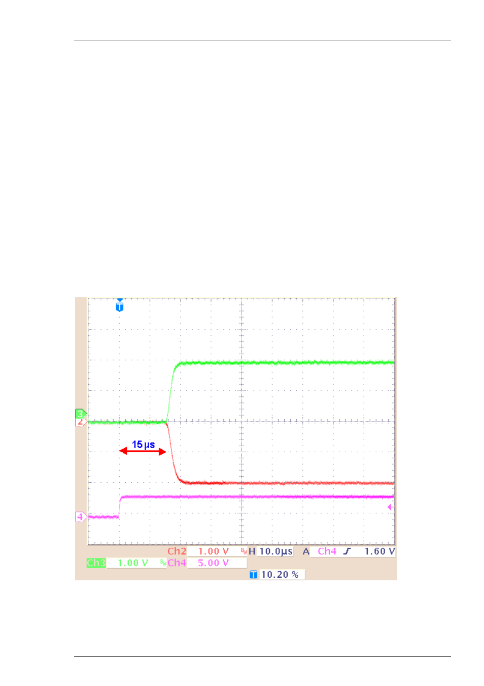
Screen shot from a standard oscilloscope triggered on the Sync Out pulse. Green trace = current
output (+I), red trace = inverted current output (I), pink trace = TTL output from the Sync Out.
Current output 200 μA and Sync Out.
The time lag between the Sync Out output and the current output is approximately
15 μs (+/- 2 μs).