Mirion Technologies TK 250 User Manual
Page 3
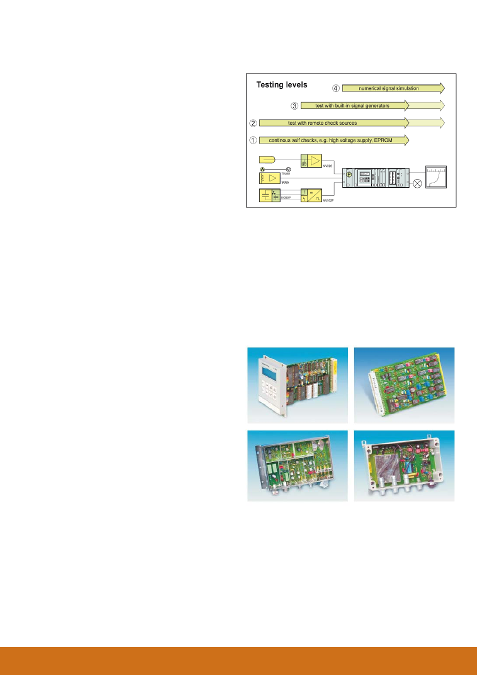
The next level (2) is the check of the complete signal
path beginning at the detector up to the interface to the
external periphery performed with remote check sources
or with ionization chambers with internal check volume.
The third level (3) is testing with electrical signal genera-
tors. Preamplifi ers and signal input boards have remote
operated pulse or current sources to generate precise
test signals for the input converters.
Finally (4), analog and binary output signals and the
concerning periphery like indicators, recorders or alarm
devices can be activated by numerical signal simulation,
thus the whole range of output signals is covered, fast
and precise. The test mode generates status signal of a
binary output (relay contact).
ELECTRONIC MODULES
The measuring channels of the systems TK 250 are
constructed with 19” modules. Pre-amplifi ers and signal
converters for very sensitive detector signals are moun-
ted in separate boxes. There is a variety of input boards
for the pre-processing of the detector signals, e.g. pulse
discriminator NI 21... and amplifi er boards NA 31... for
neutron detectors. On the output side there are isolated
buffer amplifi ers NT 31 and NT 61 for analog signals and
relay bords for binary signals, e.g. NB 21. The modules
interface, supply and auxiliary functions are assembled
all around the microprocessor boards for signal acquisi-
tion NZ 21 and for signal processing NZ 12.
TK 250
Signal Processing