3 calibration, 4 error and hardware malfunction messages, 5 resetting the instrument – Micromod Micro-DCI: 53IT5100B Micro-DCI 4-Channel Indicator Totalizer User Manual
Page 48: Alibration, Rror and, Ardware, Alfunction, Essages, Esetting the, Nstrument
53IT5100B Indicator/Totalizer
INSTRUCTION MANUAL
NOTE: When communicating with MicroMod for replacement of the main PCB, reference the
unit’s serial number to ensure the correct replacement assembly is supplied. The necessary ordering
information is provided on the instrument data tag and on the manufacturing specification sheet
supplied with that particular controller.
In the event of a hardware malfunction, a replacement PCB can be quickly substituted for the defective
assembly to minimize downtime. Contact MicroMod for instructions before returning equipment.
The defective PCB should be carefully packaged and returned, shipping charges prepaid, to the Repair Dept.
of MicroMod Automation. Do not wrap PCBs in plastic, as it can cause static damage. It is suggested that
the defective PCB be returned in the special bag in which the replacement module was supplied.
5.3 Calibration
The instrument’s analog inputs (ANI0-3) and output (ANO0) are extremely stable. They normally do not
require recalibration. If it becomes necessary to recalibrate the instrument, due to the inadvertent change of
the stored calibration values, then this can be accomplished by altering their respective datapoints. The
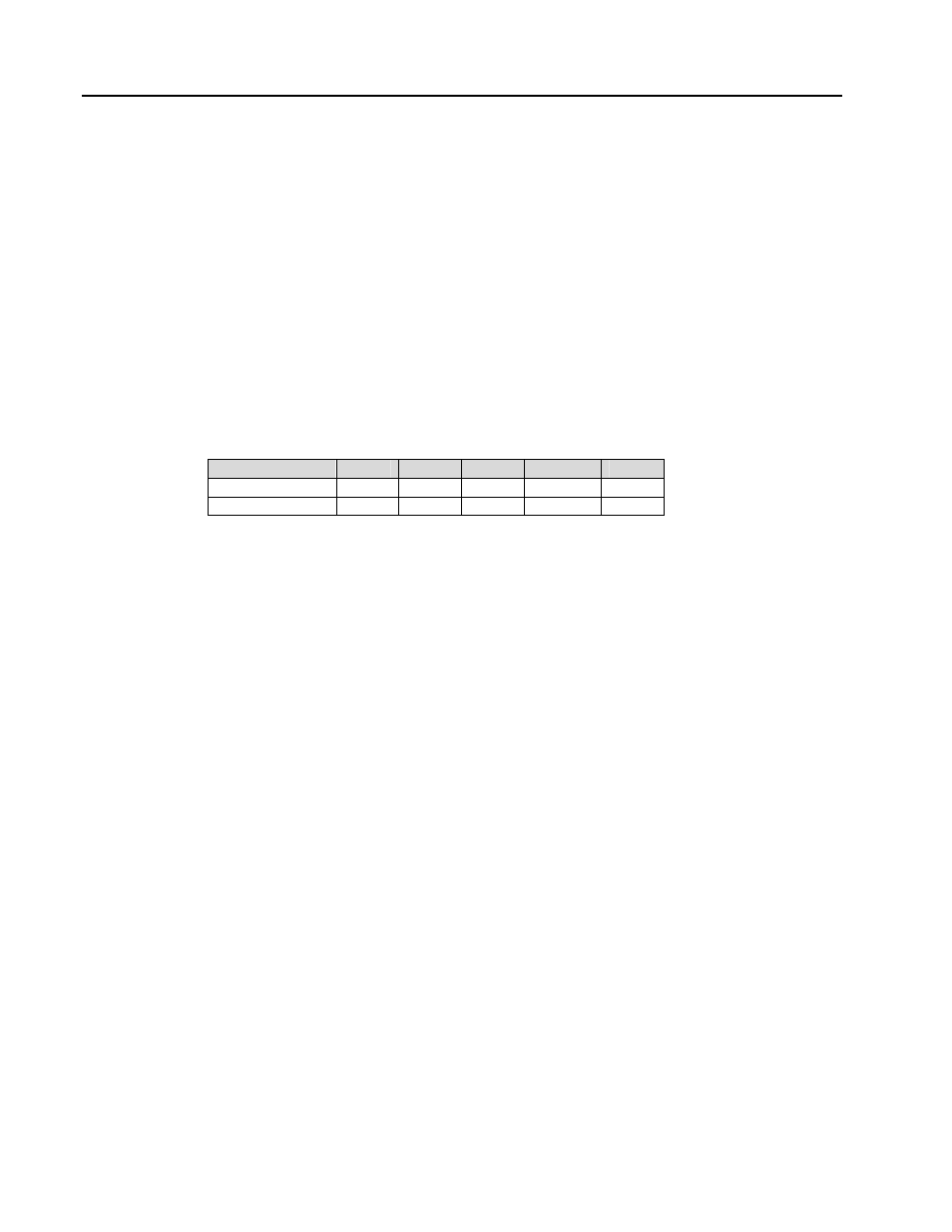
calibration span and
zero datapoint locations are as follows:
ANI0
ANI1
ANI2
ANI3
ANO0
Calibrate Zero
B263
B264
B265
B266
B267
Calibrate Span
C296
C297
C298
C299
C300
5.4 Error and Hardware Malfunction Messages
Entire Display Flashes - The watchdog timer has timed out.
CPU RAM FAILURE - IC U1 is bad.
ROM CHKS FAILURE - IC U3 is bad.
5.5 Resetting the Instrument
The instrument can be reset either by cycling the power, or by carefully pressing the reset button by inserting
a thin wire, such as a paper clip, through the small hole in the upper left corner of the front bezel. (See Figure
1-2 for the location of the reset hole.) When the instrument restarts, it immediately checks to determine if any
of the horizontal keypad push buttons are held pressed.
If
the
1 push button is held pressed during instrument reset, the instrument enters a factory test
mode. The test mode can be exited by resetting the instrument again using the thin wire with no push
buttons pressed.
If
the
2 push button is held pressed during instrument reset, the instrument database is set to the
defaulted values.
44