Programmable register overview, Programmable register quick reference – Meriam M2110L SMART LEVEL GAUGE User Manual
Page 8
9R143 Dated 3/2011
6
PROGRAMMABLE REGISTER OVERVIEW
All M2110L Smart Level Gauges have programmable registers that allow the gauge to be configured to fit the level
measurement application. Programmable registers are numbered P0 through P11. Each register controls a specific
aspect of the gauge’s performance.
Beginning on page 9 is a description of all programmable registers, and instructions for their use. Each register is
found on all M2110L Smart Level Gauge models, and performs the same function described for all models, except
as noted otherwise.
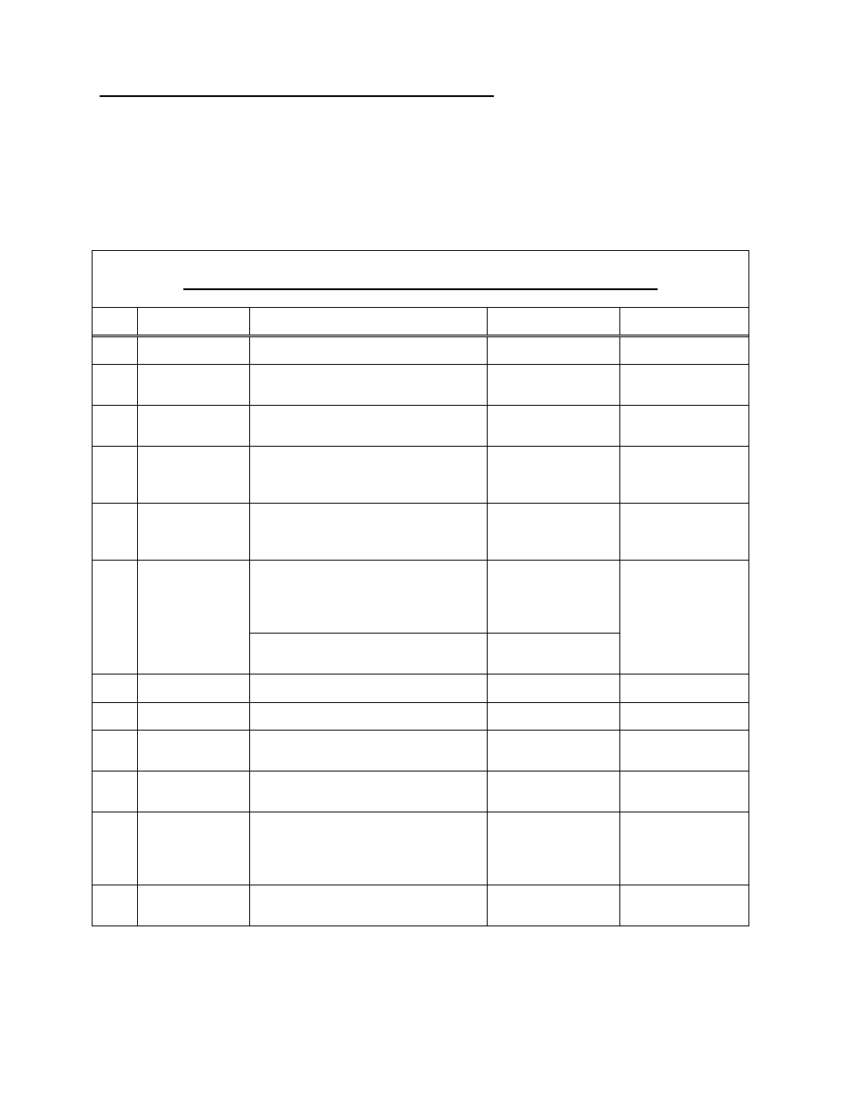
PROGRAMMABLE REGISTER QUICK REFERENCE
Px
Name
Description
Value Range
Notes
P0
Lockout Code
Lockout for security.
00 to 99
00 = Disabled.
P1
Timeout
Automatic shutoff in minutes of keypad
inactivity.
0 (disabled), 1, 2, 5,
10, 15, 25
Battery model only.
P2
Damp Rate
Exponential damping time in seconds.
0.1, 0.2, 0.5, 1, 2, 5,
10, 15, 25, 50
0.1 = No Damping.
P3
Residual
Hydrostatic
Pressure
Identifies the unmeasured or added
hydrostatic pressure due to piping
configurations.
-9,999 to +9,999
inH
2
O @ 20ºC.
+Val: Dip Tube
- Val: Direct Head
P4
Full Tank
Hydrostatic
Pressure
The pressure created by a full column
of fluid from the floor of the tank to the
top of the maximum level measured.
0 to 9,999 (Keypad)
0 to 19,999 (Serial)
Pressure in inH
2
O
@20
°C.
SetPoint Model: defines which relay
outputs are active.
0 = Disabled.
1 = SET1 only.
2 = SET2 only.
3 = Both enabled.
P5
SetPoint Options
Current Loop Model: defines the status
of the 4 - 20 mA output.
0 = 4-20 disabled
1 = 4-20 enabled
Not found on
Battery model.
P6
SET1
Controls SET1 relay or 4.00 mA value.
–20% to +120% FS
User defined value.
P7
SET2
Controls SET2 relay or 20.0 mA value.
–20% to +120% FS
User defined value.
P8
Deadband
Sets the amount of deadband in percent
of full scale for relays.
0 (disabled), 0.1,
0.2, 0.5, 1, 2, 5, 10%
SetPoint model
only.
P9
Tank Cylindrical
Capacity
The capacity, in Engineering Units, of
only the cylindrical portion of the tank.
0 to 9,999 (Keypad)
0 to 19,999 (Serial)
P9 = 0 for spherical
tanks.
P10
Tank Ends
Capacity
The capacity, in Engineering Units, of
only the dished ends of a horizontal
cylindrical tank (includes both ends).
Or, total capacity for spherical tanks.
0 to 9,999 (Keypad)
0 to 19,999 (Serial)
P10 = 0 for linear
tanks, or cylindrical
tanks with flat ends.
P11
Tank Type
Identifies type of tank.
0 = Linear/Vertical
1 = Non Linear